
Seamless deep drawn shells, cans, covers and enclosures manufactured to print in stainless steel, aluminum and copper alloys.
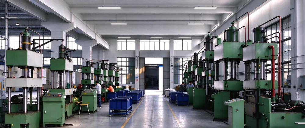
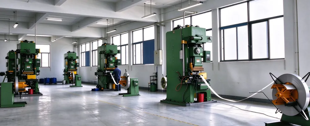
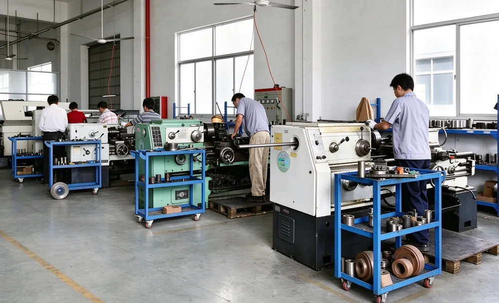
Aunov draws precision parts on 5–250T mechanical presses and 250–500T hydraulic presses — from flat coil to finished shell in one factory. Wall thickness, diameter and depth are engineered into the die before the first blank is cut, so your parts come off the press right the first time and stay right across every production run. Most parts continue through CNC trimming, welding and inspection in-house, which means one supplier controls the whole chain from material certificate to export carton.
How We Draw
Browse by Application
The same deep drawing process serves very different industries. Pick yours to see the parts we make, the materials we draw and the tests we run for it.
-
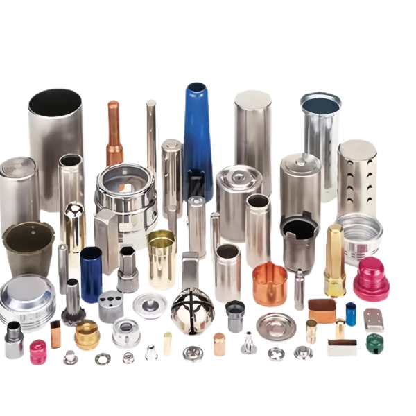
Assorted Deep Drawn Cups Tubes and Anodized Sleeves
-

Assorted Deep Drawn Shells Covers and Trays
-

Assorted Small Deep Drawn Cups and Square Shells
-
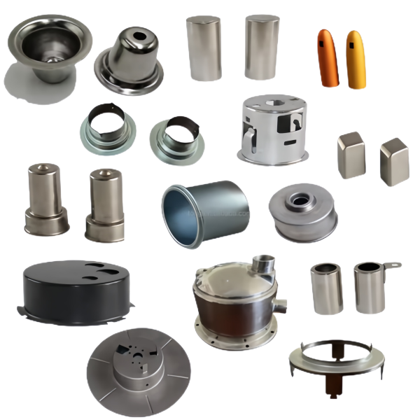
Assorted Deep Drawn Shells Caps and Motor Cups
-

Assorted Deep Drawn Caps and Cups Brass and Steel
-

Painted Deep Drawn Enclosures and Cups Assorted
-

Small Drawn Caps and Rings Family Assortment
-

Aluminum Connector Sleeves and Inserts Assortment
-

Assorted Stamped Brackets and Sheet Metal Chassis Parts
-
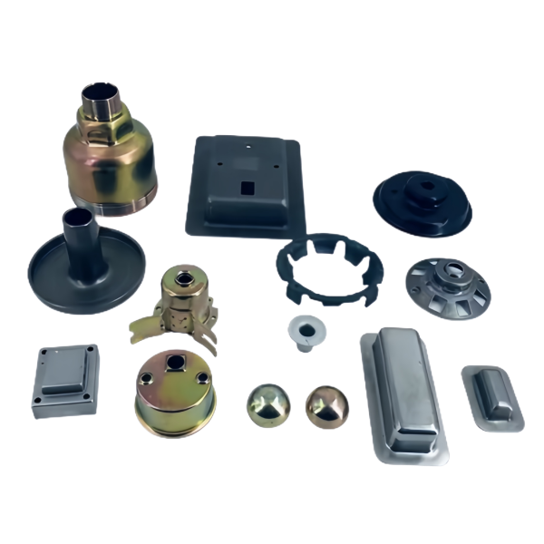
Assorted Deep Drawn Covers and Housings Zinc Plated
-

Assorted Deep Drawn Cups Caps and Sensor Shells
-

Assorted Deep Drawn Caps Plugs and T-Fittings
-

Stainless Steel Deep Drawing & Sheet Metal Forming
-
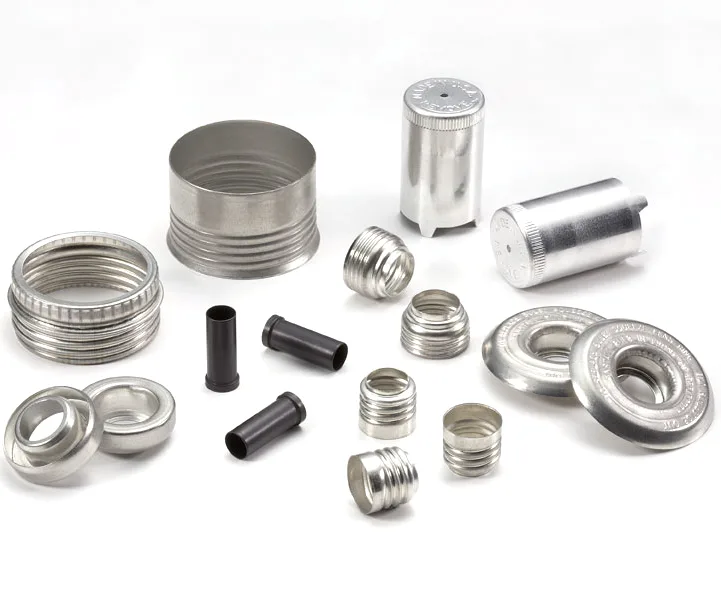
Precision Drawn and Deep-Stamped Parts
-

Automotive Seals, Grommets and Fittings Assortment
-

Drawn Cups and Covers Assortment, Steel and Brass
-

Assorted Brass and Steel Deep Drawn Plug Shells
-

Assorted Deep Drawn Cups and Vented Covers
-

Assorted Small Deep Drawn Cups Rings and Retainers
-

Assorted Deep Drawn Shells and Sensor Cups
-

Assorted Stamped Brackets Covers and Trays
-

Stainless Steel Anti-Corrosion Waterproof Time Capsule
-

Stainless Steel Durable Lock Container for Future Graduation Gift
What Is Deep Drawing?
Deep drawing is a sheet-metal forming process that turns a flat blank into a seamless, three-dimensional shell whose depth is greater than its diameter — in a single press stroke or a sequence of progressive draws. A shaped punch pulls the metal radially inward through a die, so the part is formed from one piece of material rather than welded, folded or machined.
Unlike simple bending or shallow stamping, deep drawing controls the blank-holder pressure so the wall flows without wrinkling or thinning. The result is uniform wall thickness, no seam to leak, and geometry that repeats part-to-part across production runs. It is the method of choice for enclosures, cans, caps, cartridges and pressure-bearing shells.
Specify deep drawing when the part is deeper than it is wide, must hold pressure or seal, and is needed in volume — that is where it beats machining and fabrication on cost and consistency.
The Deep Drawing Process: From Blank to Shell
Every part moves through five controllable stages. Each is monitored for wall thickness, surface and dimensional conformance so the first article and the millionth article match the drawing.
Materials We Draw: A Selection Guide
Material choice drives drawability, corrosion resistance and cost. We stock and draw the grades most demanded by electrical, HVAC, lighting and medical customers — the table maps each to where it earns its place.
Exact grade availability and drawability are confirmed at the quoting stage against your service environment and wall requirements.
Deep Drawing vs. Conventional Stamping
Both are press operations, but they solve different geometry problems. Use the table to decide which process fits your part before you brief a supplier.
For flat or shallow stamped components, see our custom metal stamping capabilities — many programmes combine both processes in one supply chain.
Frequently Asked Questions
Quick answers to the questions engineers ask before they send a drawing.
What is the minimum wall thickness you can deep draw?
We draw walls from 0.15 mm foil-grade aluminium and stainless steel up to 3.0 mm plate, with ±0.05 mm typical tolerance and ±0.02 mm available on request.
Do you make the tooling in-house?
Yes. Design, machining and try-out of progressive and transfer dies are done on our own floor, which shortens lead time and protects your intellectual property.
What draw ratios can you achieve?
Up to about 2.0 on the first pass, with redraws extending the depth-to-diameter ratio well beyond 2:1; the exact limit depends on the material and wall thickness.
What lead times should I expect?
Prototype tooling typically takes 2–4 weeks; production tooling 4–8 weeks depending on complexity, number of draw stages and surface treatment.
Can you handle plating and secondary operations?
We offer zinc, nickel and chrome plating, anodising and passivation, plus in-line piercing and threading through qualified partners under our quality system.
What production volumes do you support?
From 1,000-piece pilot runs to multi-million annual programmes on high-speed presses, with PPAP-ready documentation for automotive and medical customers.
Deep Drawing Design Rules: A Practical DFM Checklist
Most deep drawn parts are won or lost at the drawing board. A part that is easy to draw runs faster, scrapes less material, holds tighter tolerances, and costs dramatically less per piece. Before we cut the first blank, our engineering team reviews every inquiry against a short design-for-manufacture (DFM) list. The points below are the ones that move the needle most often, and they apply whether you are drawing a small sensor shell or a long, slender tube.
Corner and radius guidelines
The single most common cause of cracking at the punch radius is a corner that is too sharp for the material. As a rule of thumb, the inside corner radius at the bottom of the draw should be at least 2× to 3× the material thickness, and the outside corner radius at least 1× the thickness. When the radius drops below this, the metal has to stretch sharply around the punch nose and local necking follows. Opening the radius even slightly often turns an “impossible” part into a repeatable one. Where the geometry demands a sharp feature, we add a secondary trimming or coining operation rather than forcing it in the draw.
Wall thickness and uniformity
Deep drawing performs best when the wall thickness is uniform from top to bottom. Sudden steps in wall thickness create stress concentrations and uneven material flow. For carbon and stainless steel we routinely draw walls down to about 0.3–0.5 mm; non-ferrous metals such as aluminum, brass and copper can go thinner because they work-harden less aggressively. If your application needs a thick flange and a thin wall, tell us early — we can often achieve it by drawing a uniform shell and then reducing the wall in selected zones rather than trying to form two thicknesses at once.
Draft, taper and bottom features
A small sidewall taper of roughly 0.5°–2° makes ejection cleaner and reduces tool marks, and it is usually invisible in the finished part. The bottom can share the wall thickness or be made thicker where pressure loads are high. One constraint designers forget: holes and slots cannot be punched in the draw direction during the drawing stroke. Any feature that passes through the wall must be added in a secondary piercing operation after the shell is formed. Planning those features up front keeps the tooling simple.
Recommended minimum values by material
| Material | Min. wall (mm) | Min. inside radius (×t) | Drawability note |
|---|---|---|---|
| Stainless steel (304/316) | 0.4 | 2.5–3 | Work-hardens; may need inter-stage anneal |
| Aluminum (3000/5000) | 0.3 | 1.5–2 | Very formable, low springback |
| Brass (C260/C270) | 0.3 | 1.5–2 | Excellent draw, watch for dezincification |
| Copper (C110) | 0.3 | 1.5–2 | High ductility, soft, easy to draw |
These are starting points, not limits. With tailored tooling and staged reductions we frequently draw well beyond a single-ratio limit — see the draw-ratio discussion in our Limiting Draw Ratio reference.
Dimensional Tolerances You Can Expect
Deep drawing is unusually good at controlling radial dimensions — the diameter of the shell and the wall thickness — while axial features such as overall length are held a little looser because they depend on strip thickness and press stroke. The table below shows typical capabilities on production parts. Your actual numbers depend on material, part size, and order volume, and we will confirm them on a first-article report.
| Feature | Typical tolerance | Comment |
|---|---|---|
| Outer / inner diameter | ±0.05 to ±0.10 mm | Tight on small diameters |
| Wall thickness | ±0.02 to ±0.05 mm | Holds well after reduction |
| Length / height | ±0.10 to ±0.30 mm | Looser than diameter |
| Concentricity (ID to OD) | 0.02 to 0.05 mm | Key for sensor & valve parts |
| Roundness | 0.02 to 0.05 mm | After sizing operation |
| Surface finish (Ra) | 0.4 to 1.6 µm | Better with polished tooling |
If your specification demands more than this, we can add a sizing or ironing pass that tightens diameter and wall control further, at the cost of an extra operation. We will tell you honestly when a tolerance is worth the added step and when it only adds cost.
What is the smallest diameter you can deep draw?
For stainless steel shells we routinely produce inside diameters from about 3 mm upward, and non-ferrous parts can be smaller. Very small diameters need proportionally thin walls and carefully polished punches, so we review each micro-part on its own. If you need a tiny hermitically sealed can or a narrow sleeve, send the drawing and we will confirm feasibility.
Can you hold tight tolerances on long, slender parts?
Yes, with staged draws and an intermediate sizing operation. Long parts are more prone to wall variation along the length, so we control blank-holder pressure profile and sometimes draw in two or three reductions. Tell us the length-to-diameter ratio and the critical dimension, and we will propose the right process route.
Tooling, Dies & Our In-House Tool Room
The die is the heart of any deep drawing program. Its design decides part quality, cycle time, and how much you pay per piece. Because we design and build tooling in our own shop, we control lead time, cost, and the iterative tweaks that turn a first sample into a stable production part.
Single-stage vs. progressive dies
A single-stage die performs one draw per press stroke and is ideal for low-to-medium volumes or parts that need several reductions — each reduction may sit in its own die. A progressive die carries the blank through multiple stations in one stroke, adding drawing, trimming, piercing and forming in sequence; it suits high-volume, repeatable production where cycle time matters most. For automotive programs we often combine the two: a series of draw dies for the shell, then a progressive die for trimming and features.
Die materials and lifetime
Standard production runs use hardened tool steels (for example D2 / SKD11 class), which handle hundreds of thousands of strokes. For very high volumes we fit carbide punch and draw rings that can run into the millions of pieces with minimal wear. Polished, chrome-plated draw surfaces reduce friction and marking on stainless steel and aluminum, which matters when the visible finish is part of the specification.
Tryout, sampling and PPAP
Every new die goes through a tryout and sample stage before release. We measure first articles on a CMM, confirm material and hardness, and — for automotive customers — prepare a PPAP package (capability studies, control plan, material certificates) so your quality team can approve the process. Because tooling is built in-house, a design change that would take a vendor weeks is often a few days for us.
Surface Finish & Secondary Operations
A deep drawn shell rarely ships as-drawn. Most parts pass through one or more secondary operations that turn a raw shell into a finished component. We run these in-house so the whole job stays under one quality system.
Trimming, piercing and forming
After drawing, the flange is trimmed to length on a trimming die or CNC face mill, and holes, slots and notches are pierced in a follow-up station. Threads can be tapped or roll-formed; shallow embossing and coining tighten local features. Because piercing happens after the draw, wall integrity at the hole is preserved.
Deburring, finishing and plating
Edges are deburred by tumbling or brushing, and surfaces can be brushed, bead-blasted or left as drawn. For stainless steel we provide passivation to ASTM A967, which removes free iron and restores the passive, corrosion-resistant layer. Plating options include zinc, nickel and chrome; aluminum parts can be anodized. Where the draw work-hardens the metal, an annealing step between reductions restores ductility so the next draw does not tear.
Cleaning and inspection
Parts are ultrasonically cleaned to remove drawing lubricants before plating or assembly, and 100% or sampled leak testing is available for sealed housings. This end-to-end control — draw, finish, clean, inspect — is why customers hand us complete sub-assemblies rather than loose shells.
Do you provide passivation for stainless steel parts?
Yes. We passivate stainless steel components to ASTM A967 as a standard finishing operation, and we can certificate the batch. Passivation is recommended whenever the part will see corrosion, food contact, or a medical environment.
Can holes and threads be formed during the draw itself?
Not in the draw direction — a hole through the wall would be torn by the metal flow. Holes, slots and threads are added in a separate piercing or tapping operation after the shell is formed. Planning these as secondary operations keeps the draw stable and the features accurate.
Common Deep Drawing Defects & How We Prevent Them
Every defect in deep drawing has a known mechanical cause, which means each one is preventable with the right tool geometry, blank-holder pressure, and material condition. The table below lists the failures we watch for and the controls we apply.
| Defect | Typical cause | How we prevent it |
|---|---|---|
| Wrinkling (flange or wall) | Insufficient blank-holder pressure | Profiled BHP, draw beads, correct blank size |
| Tearing at punch radius | Radius too small, pressure too high | Open radius, staged draws, anneal if needed |
| Earing | Sheet anisotropy (grain direction) | Material cert review, trim allowance |
| Orange peel | Coarse grain, heavy reduction | Fine-grain stock, controlled reduction |
| Scoring / tool marks | Friction, grit, worn tooling | Lubrication, polished tooling, filtration |
Our process controls start before the first stroke: we certificate incoming coil, simulate the draw where geometry is critical, and profile blank-holder pressure across the stroke rather than setting it flat. The result is a stable window where good parts are the norm, not the exception.
Optimizing Cost Without Sacrificing Quality
Deep drawing is already one of the most cost-efficient ways to make a hollow metal part at volume, because it starts from flat strip and wastes little material. A few design choices push the economics further:
- Right-size the tolerance. Specifying ±0.01 mm when ±0.05 mm would do adds operations you pay for on every piece. We will flag over-tight callouts.
- Design for the draw. Generous radii and uniform walls let us skip extra reductions and sizing passes.
- Nest the blank. Better blank layout from the coil raises yield and lowers the per-part material cost directly.
- Plan volume. Tooling is a one-time cost; per-part price falls sharply as volume rises, so consolidating orders helps.
The cheapest part is the one that draws cleanly the first time and needs no rework — which is exactly what the DFM checklist above is for.
How to Choose a Deep Drawing Supplier
When you are qualifying a deep drawing partner, a short checklist separates shops that will deliver from those that will disappoint:
- In-house tooling. Building dies yourself means faster changes and no finger-pointing between vendor and toolmaker.
- Material traceability. Mill certificates, lot control, and incoming inspection protect you from substitution.
- Measurement capability. CMM, contour, and leak testing on site, not outsourced after the fact.
- Process discipline. Documented tryout, first-article, and PPAP where required.
- Communication. Engineering that tells you when a tolerance is costly, instead of quoting it silently.
- IP protection. Clear confidentiality and drawing control from day one.
We built our operation around these six points because, for a buyer, the real cost of a supplier is the cost of a part that does not fit, arrives late, or cannot be traced.
What is your typical tooling lead time?
For a standard single-stage shell, first samples are usually available within a few weeks once the drawing is frozen and material is on hand. Progressive dies and automotive PPAP programs take longer because of the sampling and validation steps. We give you a dated plan at quotation and update it as we go.
Do you sign NDAs and protect our drawings?
Yes. We sign confidentiality agreements before any drawing exchange and control drawings under a documented process. Your geometry and specifications stay yours; we only use them to make your parts.
Drawing Each Metal: What Changes Part to Part
The same drawing press behaves very differently depending on the sheet it is forming. Understanding the material is the difference between a clean shell and a cracked one, so our engineers qualify the metal before the tool is cut.
Stainless steel
Stainless steel is strong and corrosion resistant, but it work-hardens rapidly as it is drawn. Each reduction makes the metal stiffer and less ductile, so deep shells often need an inter-stage anneal to restore formability before the next draw. Lubrication must be generous and heat tint controlled, and draw radii are opened up relative to carbon steel. The payoff is a part that survives harsh, hygienic, or outdoor environments without coating.
Aluminum
Aluminum draws beautifully — low strength, high ductility, almost no springback — which lets us form complex, thin-walled shapes in fewer operations. The watch-outs are surface scratching and a tendency to gall, so tooling is polished and lubrication is clean. Architectural, lighting, and lightweight automotive parts are common aluminum deep draws.
Brass and copper
Both are highly formable and easy to draw, which makes them ideal for decorative, electrical, and plumbing components. Brass can suffer dezincification in aggressive environments, so grade choice matters; copper draws to very fine wall thicknesses and is favored for thermal and electrical parts. Both take a bright finish that needs little post-processing.
Deep Drawing vs. Other Forming Methods
Deep drawing is one of several ways to make a hollow metal part. Knowing when it beats the alternatives helps you specify the right process — and we will tell you honestly when a different method is cheaper for your volume.
If your part could plausibly be stamped, drawn or die cast, start with our side-by-side breakdown of stamping vs deep drawing vs die casting. It compares what each process can physically form, the tolerances each one realistically holds, tooling cost, and the annual volume at which each option becomes the cheaper route.
- vs. CNC machining. Machining starts from solid bar and removes most of it as chips; deep drawing starts from sheet and wastes little. For hollow, axisymmetric parts at volume, drawing is far cheaper and faster. Machining wins for low volume, tight 3D features, or when wall thickness must vary freely.
- vs. metal spinning. Spinning forms sheet over a mandrel by rotation, great for large, low-volume, symmetrical shells. Drawing is faster and more repeatable at volume and holds tighter diameter control.
- vs. casting. Casting handles complex shapes and thick sections but gives poorer dimensional repeatability and a rougher surface. Drawing delivers consistent thin walls and a clean finish for functional shells.
- vs. conventional stamping. Covered in our comparison table above — in short, drawing makes deep shells, stamping makes flat or shallow bent parts.
Quality Assurance & Traceability
For a component that seals, conducts, or carries pressure, the part is only as good as the system that verified it. Our quality loop runs from incoming coil to shipped box.
Incoming and in-process control
Every coil is received against a mill certificate and sampled for thickness, mechanical properties, and surface condition. During production we run statistical process control on critical dimensions, with check frequency set by the tolerance and volume. A coordinate measuring machine verifies first articles and periodic samples; contour and form checks catch subtle wall variation that a caliper would miss.
Leak, cleanliness and certification
Sealed housings can be 100% or sampled leak tested — helium or pressure decay depending on the requirement — and parts are cleaned to the level the application demands before plating or assembly. We keep lot traceability so any shipped batch can be tied back to its material, machine, and inspection record, which is what automotive and medical programs require.
Which process should I choose for a new part?
Send us the drawing and expected annual volume. As a rule, deep drawing is the most economical once you need more than a few thousand hollow parts a year and the shape is axisymmetric; below that, machining or spinning may be simpler. We will recommend the process that costs you less over the program, not the one we happen to push.
Can you draw parts to a specific industry standard?
Yes. We work to common standards for automotive (IATF-aligned PPAP), medical, and general industrial requirements, and we can certify material and finish to ASTM or customer specifications. Tell us the standard at quotation so it is built into the control plan from the start.
What to Send Us for a Fast, Accurate Quote
The fastest quotations come from the best drawings. You do not need a fully finished CAD model — a clear sketch with the right details is enough for a first estimate — but the more of the following you can share, the tighter our number and lead time will be.
- Geometry. A 2D drawing with all diameters, lengths, wall thickness, radii, and any tapers, plus a 3D file if you have one.
- Material. Grade and temper (for example 304 stainless steel, half-hard; 3003 aluminum; C260 brass). If unspecified, tell us the environment and we will propose it.
- Quantity. Target annual volume and batch sizes — this decides single-stage versus progressive tooling and per-part price.
- Critical dimensions. Flag the features that truly matter so we focus inspection and tolerance there rather than over-specifying the whole part.
- Finish and features. Plating, passivation, anodizing, threads, holes, or assemblies, and any cleaning or packaging requirement.
- Standard. Industry or customer specification to be met, especially for automotive, medical, or food contact.
With those six items we can usually return a firm quote and a tooling plan within a couple of working days. If something is missing, we will ask the specific question rather than pad the price for uncertainty.
Deep drawing rewards preparation on both sides: a thoughtful drawing and a capable supplier turn a sheet of metal into a precise, repeatable component at a cost stamping, machining, or casting struggle to match. That is the whole reason this process exists, and it is why we keep investing in in-house tooling, measurement, and the engineering judgment to use both well.
Limiting Draw Ratio (LDR) Reference for Deep Drawn Parts — first-draw limits by material with stated test conditions, wall-thinning data and a blank diameter calculator.
Need custom Deep Drawn Parts? Send your drawing – quotation within 24 hours.
Further reading
Before you put a cover on the press, the engineering guide below covers what the drawing has to say: draw ratios worked through step by step, material selection by service environment, the tolerances that actually hold in production, and what to specify so the first quote is the right one.