
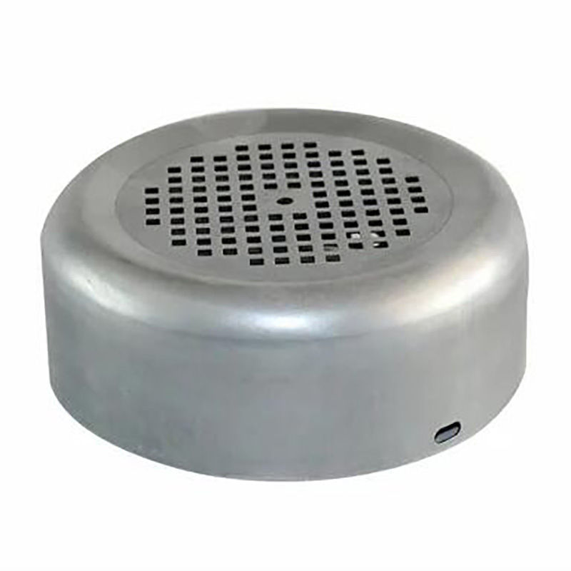
Aunov Tech builds the steel deep drawn motor bell cover with vent holes as a build-to-print part, but the geometry carries three conflicts that a generic cover never sees: a vented cylindrical wall, a flange that must seal, and a bore that locates the bearing. We treat those as three separate problems and solve each on its own operation rather than trusting a single draw to hold them all. This page explains how we keep them from fighting each other.
Holding bore-to-flange concentricity on a vented bell cover
The bearing bore and the flange outside diameter have to stay concentric within 0.05 mm total indicator reading, because the motor shaft runs through that bore while the flange bolts to the housing. A deep draw alone will not hold that relationship, so we draw the shell to +/-0.1 mm, then machine the bore and the flange pilot on the same CNC turning set-up so the two features are generated from one datum. We do not re-chuck between them, because every re-chuck is a chance to add a few microns of runout that the motor later hears as noise.
In practice the concentricity is proved on the climate-controlled CMM room at first article, then checked per batch with a dial runout fixture that reads the bore against the flange face in seconds on the line. When the drawing calls the flange pilot instead of the bore as datum A, we flip the machining sequence so the pilot is turned first and the bore is referenced back to it – the datum order in the drawing is not cosmetic, it decides which feature we cut first.
- Concentricity is proved on the climate-controlled CMM at first article, then checked per batch with a dial runout fixture that reads the bore against the flange face.
- When the drawing calls the flange pilot instead of the bore as datum A, we flip the machining sequence so the pilot is turned first and the bore is referenced back to it.
- We archive the turning offsets against the part number, so a repeat order starts from measured data instead of a fresh set-up guess.
Why the vent-hole pattern is pierced after the final draw
The vent holes let the motor breathe and equalise pressure, but piercing them into a wall that has not finished moving cracks the edge. We pierce only after the shell is fully drawn and restruck, when the wall grain is settled and the diameter is fixed. The holes run 3 to 5 mm diameter, typically six to twelve of them in a single ring, positioned where the draw wall is thickest rather than at the punch-radius corner where it is thinnest. Placing holes at the thin corner is the classic rookie error: the pierce punch locally stretches already-thin material and you get a torn, burred hole that no deburr fully fixes.
We treat hole position as a locating feature, not a cosmetic one, because the vent must clear the internal components. The sub-pierce die is mounted in the same press as the trim so the holes cannot drift relative to the flange, and the position is held to +/-0.15 mm. Burr is controlled to one side and broken by a tumble or brush pass, because a sharp vent edge becomes a noise source and a finger hazard on assembly. If the drawing wants a screened vent, we press a stainless steel mesh disc into the hole ring on a separate operation rather than trying to pierce a sub-millimetre pattern into 1 mm steel, which would destroy the wall.
- Hole position is held to +/-0.15 mm by a dedicated sub-pierce die mounted in the same press as the trim, so the holes cannot drift relative to the flange.
- Burr is controlled to one side and broken by a tumble or brush pass, because a sharp vent edge becomes a noise source and a finger hazard on assembly.
- If the drawing wants a screened vent, we press a stainless steel mesh disc into the hole ring on a separate operation rather than trying to pierce a sub-millimetre pattern into 1 mm steel.
Sealing the flange face without machining the whole envelope
The flange has to seal against the housing, but the rest of the cover does not need to be a precision surface. Machining the entire drawn envelope to a seal grade is wasted cost, so we machine only the seal land – a narrow turned face on the flange – and leave the outer flange at the as-drawn +/-0.1 mm. The seal land flatness is held to 0.08 mm and its surface finish to Ra 1.6 so an O-ring or paper gasket seats without crushing. This single decision is usually the difference between a cover that costs what it should and one that costs thirty percent more for tolerances nobody uses.
For an O-ring groove we turn the groove concentric with the bore in the same set-up, so groove-to-bore runout is governed by the machine, not by the draw. Where the customer specifies a flat gasket we leave the land wider and verify it with a blue-check against a reference plate at first article, because a blue-check shows the high spots a feeler gauge misses. Zinc or nickel plating is added after machining so the seal land keeps its finish; we mask the bore only when the plating thickness would eat into the bearing fit, and we note on the report exactly where the mask line sits.
- For an O-ring groove we turn the groove concentric with the bore in the same set-up, so groove-to-bore runout is governed by the machine, not by the draw.
- Where the customer specifies a flat gasket we leave the land wider and verify it with a blue-check against a reference plate at first article.
- Zinc or nickel plating is added after machining so the seal land keeps its finish; we mask the bore only when the plating thickness would eat into the bearing fit.
Managing wall-thinning at the shoulder of a deep bell
A bell cover is a deep shell, and the worst thinning always lands at the punch-radius shoulder where the wall turns from cylindrical to the top. We stage the draw so each pass removes a controlled slice of diameter, and we measure wall thickness at the thinnest section by micro-sectioning the first article. Acceptance is that the thinnest point stays above 82 percent of blank thickness – so a 1.2 mm SPCC blank must not drop below about 0.98 mm at the shoulder.
In-line annealing between draw stages is used whenever the cumulative reduction passes the material’s work-hardening limit, which for SPCC we budget at roughly 45 percent before the wall starts to split. The blank holder pressure is tuned per stage on the 250 to 500 T hydraulic press, because too little pressure wrinkles the wall and too much accelerates thinning at the shoulder.
- In-line annealing between draw stages is used whenever the cumulative reduction passes the material’s work-hardening limit, which for SPCC we budget at roughly 45 percent before the wall starts to split.
- The blank holder pressure is tuned per stage on the 250 to 500 T hydraulic press, because too little pressure wrinkles the wall and too much accelerates thinning at the shoulder.
- We log the shoulder wall on every first article and keep the sectioned sample on file so a field failure can be compared against the as-qualified section.
EMC and ingress: what the cover must actually keep out
The vent holes are a deliberate compromise between breathing and protection. An open 4 mm hole passes air freely but lets a probe and coarse dust through, so the real question is what the motor behind it needs. We quote the cover three ways: open vent for dry indoor duty, vent plus a pressed-in brass or stainless steel mesh for dust screening, or vent plus a snap-in breathable membrane for IP54-rated ingress with pressure equalisation. Each option changes the tooling and the unit price.
The mesh option adds a 0.15 mm woven disc retained by a rolled lip, and we pull-test a sample per batch to confirm it will not dislodge under vibration, because a loose mesh disc in a motor is a short waiting to happen. For EMC the cover itself is the shield: continuous zinc or nickel plating gives the conductive path, and we flag any bare machined edge that would break it. We do not promise an IP rating on the cover alone – it is the cover plus the customer’s gasket and the membrane that earns the number, and we say so on the first-article report.
- The mesh option adds a 0.15 mm woven disc retained by a rolled lip, and we pull-test a sample per batch to confirm it will not dislodge under vibration.
- For EMC the cover itself is the shield: continuous zinc or nickel plating gives the conductive path, and we flag any bare machined edge that would break it.
- We ask for the duty environment up front, because quoting a screened vent for a dry indoor motor adds cost the programme never uses.
How we verify a motor bell cover before it ships
Every batch of steel deep drawn motor bell covers leaves against a verification routine that is written into the first-article report and sampled on production. The checks below are the ones we actually run, not a generic quality statement, and the lot is released only when the sampled pieces pass all of them. We keep the retained first-article on file against the part number so a reorder or a field question can be answered with the actual qualified sample, not a memory of it.
- CMM report on bore-to-flange concentricity and flange pilot diameter against the drawing datum.
- Wall-thickness section at the shoulder, confirmed above the 82 percent blank-thickness floor.
- Vent-hole position and count verified on the sub-pierce die setting sheet, with burr broken to spec.
- Flange seal-land flatness and surface finish checked with a plate blue-check and roughness tester.
- Plating or finish thickness measured on the cross-section and adhesion tested by tape pull.
- Mesh or membrane retention pull-test where a screened or breathable vent was specified.
Drawing a cover like this is a chain of decisions — draw ratio, wall thinning, radii and trim. Our deep drawn covers design guide works through each of them with worked numbers.
Specifications
| Item | Steel Deep Drawn Motor Bell Cover with Vent Holes |
|---|---|
| Brand | AUNOV |
| Designing | Send us your 2D drawing, or mail a sample for measurement, our engineers reply with a manufacturability assessment and pricing. |
| Tooling | Dies engineered and produced in our own toolroom, each die held against your part number. |
| Samples | First-off samples are sent with a full dimensional report and mill certificate. |
| Materials | Carbon steel (SPCC / DC01) is the primary stock for this part, alongside 304 / 316 stainless steel, aluminium, brass and copper, with the final grade confirmed at the drawing review. |
| Surface finish | Zinc, nickel or chrome plating, e-coat, powder coat, anodising or passivation, fixed at the drawing review. |
| Processing | Progressive deep draw stages with in-line annealing as the draw ratio demands, with piercing and finish machining under the same roof. |
| Equipment | 5-250 T mechanical presses plus 250-500 T hydraulic presses, in-house CNC cells and a temperature-controlled inspection room. |
| Tolerance | As-drawn tolerance +/-0.1 mm, +/-0.03 mm after machining. |
| Delivery terms | Standard terms FOB, DDP offered to EU and US, T/T or L/C, with D/P for repeat business, blanket orders and call-offs supported. |
Frequently Asked Questions
Why must the bore and flange stay concentric on a motor bell cover?
The motor shaft runs through the bore while the flange bolts to the housing, so the two features have to hold their relationship within a tight total indicator reading. A deep draw alone will not hold it, so the bore and the flange pilot are machined on the same CNC turning set-up from one datum, with no re-chuck between them, because every re-chuck adds runout the motor later hears as noise.
Why are the vent holes pierced after the final draw?
Piercing the vent pattern after the last draw avoids distorting the holes during any further forming, so the pattern stays where the shell datum puts it. Piercing first would let the subsequent draw shift the holes out of position relative to the bore and flange.
How is the flange sealed without machining the whole envelope?
The flange face is sealed on a machined land that is referenced back to the bore datum, so only the seat is cut, not the entire outer envelope. That keeps the concentricity proved on the bore intact while still giving a flat, true sealing face.
What does a motor bell cover have to keep out?
It has to keep out ingress – water and dust – and, where the application calls for it, provide EMC shielding, while still venting as the motor needs. The vent pattern is balanced against those requirements and verified per batch with a dial runout fixture plus a CMM first article.
Related Products



Request a Quote for This Part
Send a drawing or sketch — get material advice, tooling cost and a per-piece price within 24 hours (working days).