
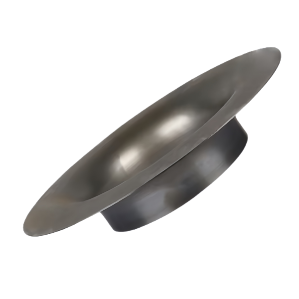
One blank, two operations: forming the dome before flaring the skirt
A domed disc with a flared skirt is two geometries with opposite metal-flow demands sharing one part. The dome is made by stretch: the punch nose pushes the blank center outward and the material thins as it takes the crown. The skirt is made by flange rotation: the outer band bends down and out along a flare line, barely changing thickness but changing direction sharply. If both happen in one stroke, the stretch at the crown and the bend at the flare line compete for the same blank and the compromise hurts both – crown thinning spikes because the flange metal is locked by the simultaneous bend, and the flare angle wanders because the dome is still moving when the skirt sets.
So we separate them. First the dome: blank, draw the crown to profile in a single hit for shallow domes or staged for deep ones, then restrike to set the contour and remove springback. At this point the part is a domed disc with a flat or slightly downturned rim. Second the flare: the disc is located on its dome profile – not on its rim – and a flare punch rolls the rim down and outward to the drawing angle, typically 20 to 80 degrees below the dome axis depending on the mating part. Locating on the dome matters: the flare line’s position is set by the tool, but its height on the part is set by where the part sits, and a disc located on a rim with trim variation transfers that variation straight into flare height.
The trim belongs between the operations, and it belongs to the flare: we trim the rim after dome forming to a diameter calculated for the finished flare, because the flare consumes rim metal as it swings outward. Trimmed too small, the skirt comes up short and the lip misses the mating groove; trimmed too large, the skirt crowds the mating ring and the assembly goes together hard.
Springback in the flare angle and how the restrike die compensates
The flare is a bending operation, and every bend springs back. On a flared skirt in low-carbon steel the springback is modest but not negligible – typically 1 to 3 degrees on a conventional flare in DC01 at 1.0 to 2.0 mm, rising with hardness, with skirt length to thickness ratio, and sharply on stainless steel. A 3 degree error on a 40 mm skirt is about 2 mm of free-end position – the difference between a skirt that clips into its groove and one that rattles.
The compensation is built into the tool, not corrected on the part. The flare die is cut with overbend – the punch angles the skirt past the drawing angle by the measured springback of the specific material lot, so the skirt relaxes back onto the drawing. The value comes from a first-article trial: flare three parts, measure the relaxed angle on the CMM, adjust, and lock the number into the tool record. For high-resilience conditions – 304 stainless steel flares can spring back 5 to 8 degrees – the die may need a coining insert at the flare line, which sets the angle mechanically by locally flattening the bend zone under high pressure; coining costs tool life but buys an angle that does not move. We also watch for asymmetry: rolled sheet is directional, and the skirt can relax differently along and across the rolling direction, leaving an out-of-round flare. Where the drawing controls skirt roundness, the fix is a sizing restrike – a ring die that irons the flare circumference after the angle is set, one extra fast operation taking ovality below 0.1 mm.
Stiffness and stress at the dome-to-skirt transition
The transition between dome and skirt is where two stiffness regimes meet. The dome is a shell – stiff, pressure-capable, resistant to dishing. The skirt is a cantilevered band – compliant by design, because its job is to flex over the mating ring or absorb assembly tolerance. The transition inherits a stiffness discontinuity, and any load that pushes on the skirt – assembly force, clamp load, vibration – concentrates bending exactly at the tangent line where the dome stops and the flare begins. That tangent is both the stiffest and the most stressed feature on the part.
Two failure modes live there. Under a single overload – a dropped part, an over-enthusiastic assembly press – the transition takes a permanent set and the flare angle changes, silently turning a snap-fit skirt into a loose one. Under cyclic load, the transition’s inner surface – stretched during forming, bent in service – is the fatigue initiation point. The countermeasures are geometric and cheap at design stage: a transition radius of at least 2 to 3 times material thickness instead of a sharp tangent, and if the duty is severe, a shallow circumferential step or bead just inside the flare line to move the stress peak away from the formed corner.
The flare mouth as a crack initiation site: rim condition control
The free edge of the flare is the most worked edge on the part and the most likely crack-start location. Consider its history: blanked (sheared, burr), drawn into the dome rim (bending and slight stretch), trimmed (a second shear, a second burr), then flared through 20 to 80 degrees with the edge fibers taking the outer-bend strain. Any burr, shear micro-crack or sliver left on that edge is a crack starter sitting in the highest strain zone of the part – flared skirts that crack in service almost always crack from the rim inward, along a line a section traces back to a trim defect.
Edge discipline is explicit in our route:
- Deburr between trim and flare, always. The edge entering the flare die is deburred on both faces; a burr on the outer fiber of the bend is the single most common cause of longitudinal rim cracking.
- Trim quality is monitored, not assumed. Trim clearance – around 5 to 10 percent of thickness per side on steel – is checked on the first piece of each run by examining the shear band and rollover on a sectioned sample; a worn trim die produces a rolled edge with hidden tearing.
- Flare edge strain is bounded by the development. Trim diameter versus skirt length versus angle is chosen so the edge fiber strain stays inside the material’s bend limit – an aggressive short skirt at a steep angle leaves no margin, and the development report shows the number.
- First-article rim check under magnification: one part flared, sectioned radially, rim bend inspected for orange peel, micro-cracks and thinning. Acceptance is no visible cracking and edge thinning within the agreed band. For stainless steel or tempered parts the rim check graduates from good practice to release criterion, because those materials have less forgiveness between a marginal edge and a cracked one.
Retention and snap fit duty: how the flare diameter drives engagement
In many assemblies the flared skirt is the fastener: the disc is pushed into a bore or over a ring, the skirt flexes out and snaps back behind a shoulder, and the dome holds the assembly together – lamp optics, trim covers, filter retainers, speaker bezels. When that is the duty, the flare diameter is not a cosmetic dimension; it is the preload. Engagement works as a system of three tolerances: the flare’s outside diameter, the mating shoulder’s diameter, and the skirt’s effective stiffness from material modulus, thickness and free length. Too little interference and the disc falls out; too much and the skirt takes a permanent set on the first push, so the second push fits loose even if the first succeeded.
We build retention on data. The drawing sets flare diameter with tolerance – we hold ±0.1 mm as-drawn, and where retention is critical the skirt gets a sizing restrike and a tighter band. At first article we measure push-in and pull-out forces on a force gauge, on parts built at nominal and at both tolerance extremes of the skirt diameter, and the force window is written into the acceptance criteria – typically a minimum pull-out force, a maximum push-in force, and ten consecutive push-pull cycles inside the window to prove the skirt is not yielding.
How we verify dome height, flare angle and rim integrity
Release for this geometry is a profile-and-function check, not just a diameter:
- Dome profile by meridian trace on the CMM against the CAD contour – crown position, dome height and profile band, with acceptance to the drawing.
- Flare angle at a minimum of four positions around the skirt, on the CMM or an angle gauge fixture; acceptance within the drawing band, and the four readings within 0.5 degree of each other to catch asymmetric springback.
- Skirt diameter and roundness at flare mouth and flare root; roundness acceptance typically 0.1 mm after sizing where the drawing calls for it.
- Flare height and rim position relative to the dome, from the same locating datum used in the flare die, so the measurement chain matches the tooling chain.
- Rim integrity by radial section on a first-article part – micro-cracks, orange peel, edge thinning against the agreed limit – and in production by visual rim inspection against a boundary sample.
- Retention forces where the skirt snaps: push-in and pull-out on a force gauge at first article and on the sampling plan, including parts at the skirt diameter tolerance extremes.
- Wall thickness at dome flank, transition and mid-skirt by ultrasonic or section, bracketing the transition as the reference station.
- Records: dimensional report with the four-position angle table, material certificate per heat, and the locked overbend value from the flare development archived with the tool file.
The design decisions behind a part like this — draw ratio, wall thinning, radii and trim — are worked through with numbers in our deep drawn covers guide, and the Precision Deep Drawn Parts pages collect the rest of the family.
Specifications
| Item | Steel Deep Drawn Domed Disc with Flared Skirt |
|---|---|
| Brand | AUNOV |
| Designing | A drawing file or a physical sample starts the review, DFM feedback is returned with the quote. |
| Tooling | Our own toolroom designs and builds every die, stored under your part number. |
| Samples | The first-article set ships with dimensional data and material certs. |
| Materials | Carbon steel (SPCC / DC01) leads the stock list for this part, alongside 304 / 316 stainless steel, aluminium, brass and copper, with grade selection confirmed at drawing review. |
| Surface finish | Plating, e-coat, powder coating, anodising or passivation as the drawing calls out, selected against the drawing requirement. |
| Processing | Staged deep drawing with in-line annealing where needed, with piercing and finish machining under the same roof. |
| Equipment | Mechanical presses 5-250 T and hydraulic presses 250-500 T, CNC cells plus a temperature-controlled CMM room. |
| Tolerance | Drawn tolerances held to +/-0.1 mm, +/-0.03 mm after machining. |
| Delivery terms | FOB standard, DDP offered for EU and US, T/T and L/C; D/P on repeat accounts, call-off schedules and blanket orders supported. |
Related Products


Frequently Asked Questions
Why split the dome and the flare into two operations?
The dome is made by stretch and the skirt by flange rotation; doing both in one stroke makes them compete for the same blank, spiking crown thinning and wandering the flare angle.
How is the flare located?
The disc is located on its dome profile, not its rim, so trim variation does not transfer into flare height – the flare line position is set by the tool.
What flare angles are typical?
Typically 20 to 80 degrees below the dome axis depending on the mating part, set by the flare punch and confirmed on the first article.
What steel is the disc made from?
Carbon steel such as SPCC and DC01 and stainless steel 304 and 316, drawn with in-process annealing so the wall thins evenly across the dome.
Request a Quote for This Part
Send a drawing or sketch — get material advice, tooling cost and a per-piece price within 24 hours (working days).