
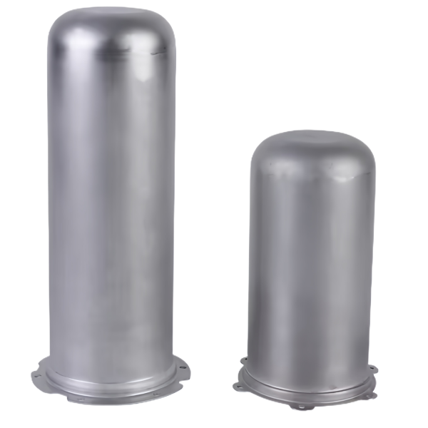
Why a dome end outperforms a flat bottom under internal pressure
A cylindrical sleeve with a domed end is a pressure vessel question before it is a forming question. When a closed-end sleeve holds pressure – an accumulator component, a pneumatic barrel, a damper tube – the end cap carries the full load, and its geometry decides the stress state. A flat bottom puts all the pressure force into plate bending: stress grows with the square of diameter and inversely with the cube of wall thickness, which is why flat-ended tubes are limited to low pressure or need welded end plates. A domed end replaces bending with membrane tension – the load resolves into tensile stress spread through the shell – and for equal wall thickness a hemispherical or elliptical dome carries several times the pressure of a flat closure.
The forming route delivers this in one piece: a dome drawn from the same blank as the cylinder has no weld seam at the crown, no heat-affected zone, no crevice to trap media – the failure modes that dominate welded end caps do not exist. We form dome-end sleeves in SPCC or DC01 as standard, with 304 and 316 stainless steel as the upgrade path for corrosive media. In the feasibility review we calculate the dome’s membrane stress at your working plus proof pressure against the sheet’s post-forming strength – and the calculation uses the formed dome thickness, not the sheet nominal, because the dome is stretched during forming. A dome thinned 15 percent at the crown has 15 percent less pressure margin, and nobody should discover that in test.
Dome thinning: where the wall loses thickness and by how much
The crown of a drawn dome is the most stretched region on the part. Metal at the blank center is biaxially stretched over the punch nose; it does not flow in from the flange the way wall metal does. The result is predictable thinning concentrated at the crown, recovering toward the tangent line. On a single-stage shallow dome in low-carbon steel we typically see 8 to 12 percent thinning at the crown on a well-tuned die; a deep dome drawn in stages without annealing can exceed 20 percent unless the nose radius is opened up and the binder force tuned down to let metal flow inward.
Thinning is not a defect – it is a designed outcome with an acceptance band, because it controls the pressure margin at the crown, the fatigue life of the dome, and the buckling behavior under external pressure or vacuum. Our practice on dome-end sleeves:
- The thinning band is quoted before tooling is cut – typically a minimum of 80 to 85 percent of nominal wall at the crown for single-stage domes, agreed against your pressure case.
- Punch nose radius is the main lever. Below about 5 times sheet thickness the nose concentrates stretch and spikes thinning; opening the radius spreads it over a wider band and can cut peak thinning by a third.
- Lubrication and binder pressure are the secondary levers. Drawing oil with the right film strength and a binder set just above wrinkle threshold feed the flange inward so the crown does less of the work alone.
- Deep domes with tight limits get staged draws with interstage annealing – routine here for depth-to-diameter ratios above roughly 1.0, on 250 to 500 ton hydraulic presses whose slow, controlled stroke keeps the strain rate inside the material’s window.
Holding a sleeve wall inside band across multiple draw stages
Deep sleeves are made by staged reduction: each stage redraws the cup into a smaller diameter and greater depth. The ratio per stage comes from the material’s limiting draw ratio – roughly 1.6 to 1.8 for annealed low-carbon steel in the first draw, tightening to 1.2 to 1.35 in redraws. What the ratio does not show is the ironing effect: if die-punch clearance is set below the incoming wall thickness, the wall is deliberately squeezed thinner and longer; if clearance is open, the wall keeps thickness but depth comes only from diameter reduction. Sleeve customers usually want depth without thinning, so we hold clearance just above the incoming wall in early stages and iron only where the drawing asks for a specific finished wall.
Stage-to-stage consistency makes the sleeve repeatable. We archive four settings per stage under your part number: binder force, punch speed, lubricant type and application, and die set identity with its maintenance count. A reorder rebuilds the route from the archive instead of re-tuning on the floor. Wall thickness is tracked at five fixed heights – just below the open end, mid-wall, dome tangent, dome flank, crown – because a drift that starts at one station shows up first at one height, and the height tells us which die ring to check. Annealing belongs to the route, not the rescue kit: when accumulated strain approaches the material’s limit, the next redraw tears at the corner radius, so we schedule interstage anneal from the reduction plan before the first die is cut – typically after the second or third redraw for carbon steel.
The dome-to-cylinder transition radius and its role in fatigue life
Between dome and cylinder wall there is a transition, and on pressure-cycling sleeves that transition is the fatigue-critical location. The geometry changes curvature there, so the membrane stress field must turn a corner, and the corner collects bending stress on top of membrane stress. A sharp transition – small radius, or a visible kink – is a classic stress riser: fatigue cracks in drawn pressure sleeves almost always initiate at the dome tangent, on the inside surface, where bending adds to pressure stress and the surface has seen the most forming strain.
We control the transition three ways. The die is cut with a transition radius no smaller than 3 to 5 times sheet thickness, larger where the fatigue spectrum is severe – the cost of a larger radius is a slightly longer dome, usually free in the blank. The restrike that sets the final dome profile is gauged specifically at the tangent with a meridian profile check against CAD, because a worn die relaxes the radius gradually and the drift is invisible to a depth gauge. And the inside surface is protected: any scratch, tool mark or scale pit along the transition is an initiation site, so descaling and handling between stages is written into the route, and for severely cycled parts we can add a light internal polish or shot-peen at the dome interior to put the surface into compression. When you supply the duty cycle – pressure amplitude, cycles per hour, target life – we run the transition through a fatigue check against post-forming properties and tell you whether the standard radius clears it. That calculation costs one email and saves a validation test.
Trimming and squaring the open end of a long drawn sleeve
The open end does not come off the press finished. Drawing drags the rim unevenly – the wall grows in lobes, the earing pattern of rolled sheet leaves high and low spots, and the rim can wave several tenths of a millimeter on a deep part. Every sleeve gets a trim, and on precision work a square-up. Trim method is a tolerance decision: a conventional trim die is fast and holds the cut line to about ±0.1 mm, which suits sleeves that weld or crimp into the next assembly; a machined square-up on a turning centre holds length to ±0.03 mm and rim squareness to the axis under 0.05 mm over the diameter, which a sleeve needs when it seats against an internal shoulder or carries a seal.
Earing drives material cost: directional sheet ears at four or more points around the rim, and the trim removes the ears, so the blank must be oversized by the earing height. Normal-annealed low-carbon steel ears 1 to 3 percent of rim diameter; heavily work-hardened or cross-rolled stock can double that. Where volume justifies it, blank development shapes the blank to counter earing rather than paying the penalty in every stroke. The rim edge is deburred on both faces – the inner burr is the dangerous one, because it faces the pressure cavity and becomes both a contamination source and a crack starter.
How we verify dome profile and wall thickness on dome end sleeves
Each part number carries a written measurement plan, released with the first article and re-run on the agreed sampling basis:
- Profile scan of the dome – a meridian trace on the CMM from open end to crown, checking contour against CAD with attention to the transition radius and crown position. Acceptance: profile within the drawing band, transition radius above its stated minimum.
- Wall thickness map by ultrasonic or sectioned micrograph at the five fixed stations – open end, mid-wall, tangent, dome flank, crown. Acceptance: every station inside the thinning band, crown not below its floor.
- Diameter and ovality at two or more heights in the cylinder section; ovality on a roundness check is the early warning before diameter drifts out.
- Length and rim squareness after trim or machining, gauged per the agreed class – ±0.1 mm as-trimmed, ±0.03 mm machined.
- Burr and surface condition at the rim and dome interior against a retained boundary sample; the inner surface of the transition is inspected for marks that would seed fatigue.
- Pressure verification where the drawing calls for it – proof-pressure test on a sampled basis with hold and visual re-check, the record filed with the batch.
- Material traceability – mill certificate per heat, matched to the draw record and stage settings archive, so the route from coil to finished sleeve is one retrievable file.
Not sure whether to draw, machine or weld this geometry? The guide to deep drawn covers compares the three routes and shows where each one wins; the full Precision Deep Drawn Parts range is linked from the overview page.
Specifications
| Item | Steel Deep Drawn Dome End Cylindrical Sleeves |
|---|---|
| Brand | AUNOV |
| Designing | Send the drawing, or a sleeve sample we can measure, a manufacturability review comes back with the quotation. |
| Tooling | Dies engineered and produced in our own toolroom, with your part number on the tool record. |
| Samples | Samples for approval come with dimensional data plus material certs. |
| Materials | Carbon steel (SPCC / DC01) is the primary stock for this part, alongside 304 / 316 stainless steel, aluminium, brass and copper, and the grade is fixed at the drawing review. |
| Surface finish | Surface treatment per the drawing: plating, e-coat, powder coating, anodising, passivation, as called out on your print. |
| Processing | Multi-stage drawing, annealed in line where wall thinning calls for it, pierced and machined on the same floor. |
| Equipment | Mechanical presses 5-250 T and hydraulic presses 250-500 T, CNC turning and milling cells, a climate-controlled CMM room. |
| Tolerance | As-drawn tolerance +/-0.1 mm, +/-0.03 mm after machining. |
| Delivery terms | FOB as standard, DDP available for EU and US destinations, T/T and L/C; D/P on repeat accounts, call-off schedules supported. |
Frequently Asked Questions
Why does a dome end outperform a flat bottom under pressure?
A flat bottom puts the load into plate bending, limited to low pressure or welded plates; a domed end resolves the load into membrane tension spread through the shell, carrying several times the pressure for equal wall. The dome is drawn from the same blank, so there is no weld seam at the crown.
Where does the wall thin on a dome-end sleeve, and by how much?
The dome stretches most at the crown during forming, so the formed thickness – not the sheet nominal – sets the pressure margin; a crown thinned 15 percent has 15 percent less margin. The feasibility review calculates membrane stress at working plus proof pressure against post-forming strength.
Which materials are used for dome-end sleeves?
SPCC or DC01 as standard, with 304 and 316 stainless steel as the upgrade path for corrosive media. The dome-to-cylinder transition radius is set for fatigue life, not just appearance.
How is a dome-end sleeve verified?
Dome profile and wall thickness are measured along the draw, with the transition radius checked for fatigue. The typical minimum order is 1,000 pieces with a 24-hour quotation.
Related Products


Request a Quote for This Part
Send a drawing or sketch — get material advice, tooling cost and a per-piece price within 24 hours (working days).