
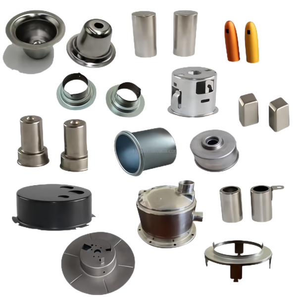
The Assorted Deep Drawn Shells Caps and Motor Cups page is not one part: it is the mixed reality of most of the orders we run on the drawing floor, where a customer needs open shells for one sub-assembly, close-fitting caps for another, and motor cups with a controlled wall for a third, all released on one purchase order and shipped in one container. Running an assortment well is a different discipline from running one part at high volume. This page covers how we plan the blanks so the whole family nests on the same coil, how we sequence changeovers so the mix does not eat the schedule, where motor cups demand tighter wall control than the rest of the batch, and how annealing is scheduled when the assortment spans two different mill systems in the same crate.
Caps, shells and motor cups share a blanking discipline
An assortment quote begins with a blanking plan, not with individual dies. Shells, caps and motor cups of different diameters can often share strip layout on one coil width if the diameters are chosen with nesting in mind, and a shared coil width means one feed line, one lubrication setting and one scrap rate instead of three. When a customer sizes a family of parts, we regularly ask for a millimetre here or there – a cap at 47 mm instead of 45, a cup at 96 instead of 98 – because the round parts then interleave on the strip and the material utilisation jumps from the low 70s to the high 80s in percent.
What the blanking plan fixes for each part in the family:
- Blank diameter, computed per part from surface area and wall movement, then rounded to a nestable value rather than a convenient one – a 0.5 mm change in blank diameter moves the draw ratio, so every change is re-checked against the limit diagram before the tool is cut.
- Strip width and pitch, common across the family where possible, so the same feed and piloting hardware runs every part.
- Scrap skeleton, which is weighed per shift as a cross-check on yield; a skeleton that suddenly gets heavier means a die is cutting a different blank than the layout says it should.
Caps deserve one extra line: they are the family members most sensitive to blank diameter error. A cap that fits over something usually carries a snap or friction feature whose retention force is set by the interference, and a half-millimetre of blank drift moves that interference far more than it moves a shell’s overall height.
Changeover economics on a mixed drawn-parts order
A draw die changeover is slow by stamping standards: the die has to be trued to the ram, holder pressure re-established, lubrication re-tuned, and the first parts scrapped until the system reaches thermal and frictional equilibrium. On a mixed order the temptation is to run big lots of the easy part and squeeze the hard one between them; we schedule the opposite way, because the hard part is where setup hours actually buy quality.
The sequencing rules that have held up across mixed jobs:
- Run the part with the tightest wall tolerance first after setup, while the press is warm and the lubrication film is stable, and run the loosest part last, when drift has crept into everything.
- Group parts that share a blank diameter so the feed line is not re-pitched between them; a pitch change is a twenty-minute error window in which the die can close on a misplaced blank and take an edge with it.
- Hold the last five good parts of each part number as the setting master for the next run, so the next changeover starts from a measured condition rather than a written recipe alone.
Customers who release assortments on call-off schedules get the added benefit that the dies stay resident in the toolroom under their part numbers, so a changeover is a die-set exchange rather than a rebuild – the difference between a two-hour and a two-day changeover, and why we resist returning mixed-family tooling to general storage between runs.
Motor cups carry the tightest wall control in this assortment
An open shell can be a quarter millimetre off on wall and nobody notices; a motor cup cannot. Inside a motor it sets the air gap geometry around the winding and often carries a bearing at one end, and its wall thickness varies with how metal flows off the punch nose – thicker at the rim where material piles up, thinner near the wall-floor junction where the draw concentrates strain. A plain drawn cup varies 10-15 percent of nominal thickness over its height; on a motor cup we stage the draws to stay inside a much tighter band, because the cup may be machined afterwards and the stock must exist everywhere the cutter will reach.
The specific controls that separate motor cups from the rest of the assortment:
- Draw staging: a motor cup that could theoretically be drawn in two hits is drawn in three when the wall band matters, trading press hours for a strain path that never approaches the thinning limit.
- Blank holder profile: the holder is stepped or beaded locally to brake the flange where flow is fastest, because on a round cup the rim feeds unevenly and the wall inherits that unevenness directly.
- Punch nose radius: held generous in early stages and tightened only at the final hit, since the nose radius is where wall thinning concentrates – a radius cut one size too small shows up as a measurable thin band just above the floor on the very first ultrasonic scan.
- Wall measurement: on motor cups we measure wall thickness at fixed heights on multiple meridians, not just at the open end, because the worst wall is usually a third of the way up from the floor and never sees a pair of calipers unless someone goes looking.
When the motor cup is the part in the assortment that gets secondary machining – a bored bearing seat, a turned rim – the machining happens on the same floor as the drawing, which matters more than it sounds: a wall that drifted in drawing is discovered by the machinist within the hour, not by the customer after the parts have crossed an ocean.
Annealing strategy when one assortment spans two mill systems
A mixed crate often holds carbon steel cups and stainless steel shells side by side, and the annealing question is where those two may meet in the schedule. SPCC and DC01 anneal at 650-700 °C in a protective atmosphere; 304 stainless steel is solution annealed at 1050-1100 °C and quenched. Running both through one batch furnace is how carbon steel comes out scaled and stainless steel comes out sensitized, so the two never share a basket; the schedule runs them on different days, or stainless steel last with a full purge and atmosphere qualification in between.
The rules we apply to in-process annealing on assorted orders:
- Intermediate anneals are triggered by accumulated strain, not by die count – a two-hit cup in thin material may need one and a five-hit tube in thick material may need none, so the anneal points are per part, set at the process design review and printed on the router card.
- Every annealed batch is identified with heat-treat lot numbers that follow the parts through the remaining draws, so if a furnace parameter is later questioned, the affected cups can be quarantined by lot rather than by suspicion.
- Critical-to-function parts in the assortment – the motor cups again – get a hardness or grain-size check after the final anneal, because a coarse grain from overheating will show up as an orange-peel surface on the next draw, and orange peel on a bearing seat is a rejection waiting to happen.
Where the drawing allows it we also substitute a stress-relief for a full anneal on the carbon steel members of the mix, at 550-600 °C: it recovers enough formability for the remaining hits while keeping the surface clean enough to skip an acid pickle, which removes a whole wet-processing step and its associated handling damage from the middle of the schedule.
How we verify a mixed assortment of drawn parts before it ships
A mixed release is verified part by part against its own control plan, then verified again as an assortment, because the failure mode unique to mixed orders is mix itself – the wrong cup in the right box. Each release is documented as follows:
- Per part: first-off and in-process dimensional checks per the control plan, with wall thickness on motor cups measured at fixed heights by ultrasonic or section on the first article, and height, rim diameter and concentricity on every setup sampled across the run.
- Material traceability: mill certificates per heat matched to part numbers in the assortment, with the anneal lot numbers from intermediate treatment recorded on the router so the whole history reads forward from coil to crate.
- Wall and strain evidence on motor cups: a thickness map on the first article and a reduced map on a sampling basis in production, confirming the thin band above the floor radius stays inside the drawing’s minimum wall.
- Surface condition per the specified finish: plating, e-coat or passivation verified on the parts that carry it, with thickness readings on flat references and adhesion or stain tests per the relevant ASTM method.
- Assortment integrity: a final packing check that each bag, layer or box carries the right part number and quantity, with weights used as a secondary count on high-volume small parts.
The shipment report is organized by part number so incoming inspection can sample each family member independently, and retention samples are filed the same way, so a question raised months later about one member of the assortment is answered without re-opening the whole batch.
If you are weighing drawing against machining or welding for this geometry, the guide to deep drawn covers sets out where each route wins; the full Precision Deep Drawn Parts range is linked from the overview page.
Specifications
| Item | Assorted Deep Drawn Shells Caps and Motor Cups |
|---|---|
| Brand | AUNOV |
| Designing | Send drawings, or send a cup sample to be measured, a manufacturability review comes back with the quotation. |
| Tooling | Dies engineered and produced in our own toolroom, stored under your part number. |
| Samples | Sample parts arrive with a dimensional report and material certification. |
| Materials | Standard stock is carbon steel (SPCC / DC01), 304 / 316 stainless steel, aluminium, brass and copper, and the grade is fixed at the drawing review. |
| Surface finish | Plating, e-coat, powder coating, anodising or passivation as the drawing calls out, per the drawing. |
| Processing | Staged deep drawing with in-line annealing where needed, with piercing and finish machining under the same roof. |
| Equipment | Mechanical presses 5-250 T, hydraulic presses 250-500 T, in-house CNC cells and a temperature-controlled inspection room. |
| Tolerance | Drawn tolerances held to +/-0.1 mm, machined features held to +/-0.03 mm. |
| Delivery terms | FOB is standard; DDP offered for EU and US, payment T/T or L/C, D/P for repeat accounts, call-off schedules supported. |
Frequently Asked Questions
How do caps, shells and motor cups share a blanking plan?
They begin with one coil-width layout rather than separate dies; diameters chosen with nesting in mind interleave on the strip and lift material utilisation from the low 70s to the high 80s in percent, so a single feed line serves the family.
Which part in the assortment carries the tightest wall control?
Motor cups usually carry the tightest wall and bore control because they locate a rotating assembly; the drawn body holds the family tolerance while the critical seat is CNC-finished. The assortment is quoted by the hardest part, not the average.
How is annealing handled when an assortment spans two mill tempers?
Each metal’s anneal is scheduled by its own temper and thickness so the softer alloy is not over-cycled while the harder one is under-annealed, and batch records keep the two routes separate and traceable.
How is a mixed drawn-parts order quoted and inspected?
A shared blanking plan sets the line, and CMM first articles plus batch samples confirm each geometry. The typical minimum order is 1,000 pieces with a 24-hour quotation.
Related Products



Request a Quote for This Part
Send a drawing or sketch — get material advice, tooling cost and a per-piece price within 24 hours (working days).