
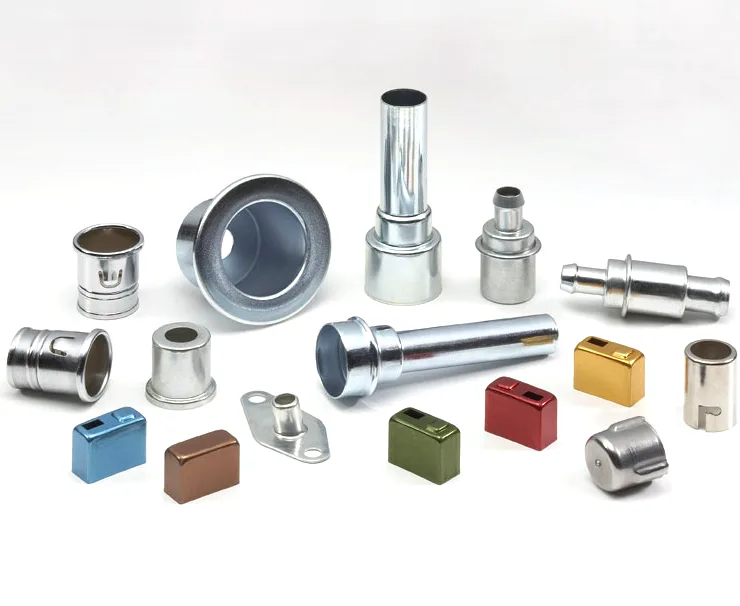
A connector sleeve has to be right twice: once electrically, once thermally
An aluminium connector sleeve, or insert, is a small part that is often specified by its ID and its length and nothing else, and that is precisely the specification which will not work. A sleeve that carries a conductor has to do two quite different jobs at once – it has to make an electrical connection, and it has to carry heat away from that connection. Those two jobs pull in opposite directions on almost every dimension, and a sleeve designed for one will fail at the other.
We deep draw on maintained presses with blank size and lubrication logged per run, and batch records filed so a repeat order starts from approved data, on a press shop running 5-250 T mechanical and 250-500 T hydraulic presses with annealing ovens on site, CNC turning centres for secondary operations, and CMM inspection. Turned secondary features to +/-0.03 mm and as-drawn walls to +/-0.1 mm, with critical dimensions carrying CMM data with the shipment. Stock runs to carbon steel, 304 and 316 stainless steel, aluminium and brass, with the final grade fixed at the drawing review. Plating, powder coating, anodising or polishing per the print, with finish thickness and adhesion checked on the first article. This page is about the two jobs and the dimension that has to serve both.
The electrical job: the ID sets the contact
Where a sleeve carries a conductor, the electrical path depends on the ID in four ways, and each one is a requirement:
- The ID’s size sets the interference. A sleeve that is a close fit on the conductor makes a good low-resistance connection by contact pressure. A loose fit relies on a plating or a coating to bridge the gap, and that is a much less reliable mechanism. So the ID’s tolerance is an electrical requirement, not just a dimensional one.
- The ID’s surface condition matters. An oxide on the conductor or on the sleeve’s bore is an insulator. Aluminium is particularly prone here – its oxide is a good insulator, which is exactly why aluminium conductors are always terminated with a mechanical clamp rather than relying on bare contact. A sleeve that is intended to make bare contact has to specify a surface preparation or a plating that prevents oxide.
- The ID’s length sets the contact area, and therefore the contact resistance and the current-carrying capacity. A short sleeve runs hotter.
- The ID’s surface finish sets the contact behaviour. A smooth bore gives consistent contact; a knurled or serrated bore bites into the conductor and gives a gas-tight connection – which is what a high-current or a high-vibration application needs, and which damages a conductor designed to be removed and re-terminated.
The thermal job: the OD carries the heat away
A connector that carries real current generates heat at the contact, and that heat has to get out. The sleeve is often the main path, which means the OD is a thermal design variable:
- Conduction along the sleeve’s wall. Aluminium’s thermal conductivity is around four times copper’s and twenty times stainless steel’s, which is why aluminium is the standard choice for a power connector sleeve where heat removal matters. If the sleeve is stainless steel, its thermal resistance is a genuine design penalty and it should be in the calculation.
- Conduction into whatever the sleeve sits in. Often a better heat path than the sleeve’s own outer surface, which is why the sleeve’s mounting diameter and its surface contact with the housing may matter more than its own surface area.
- Convection from the outer surface. The least effective of the three paths, but on a free-standing sleeve it may be the only one. A sleeve with a fin or a flange is designed to increase this path.
- The wall’s thickness is the compromise. A thicker wall conducts better axially but conducts more heat radially into the housing – which is usually good. The interesting case is a very thin wall needed for a low-resistance crimp or a tight interference, and there the thermal performance has to be recovered elsewhere.
Where the two jobs conflict
This is the useful part, because the conflicts are where the design needs decisions:
| Material | Aluminium conducts heat about twenty times better than stainless steel, so it is the better thermal answer by a wide margin. Copper conducts better still but is heavier, more expensive, and harder to form into a drawn sleeve. A copper-alloy sleeve is a reasonable compromise where the current is high and the mass is not critical. |
|---|---|
| ID size versus wall thickness | A thin wall is needed for a tight interference or a low-resistance crimp, and a thick wall conducts better. Where both are needed, a heavier conductor or a better path to the housing is the answer rather than compromising the interference. |
| Bore finish versus contact reliability | A serrated bore gives excellent contact but damages the conductor. A smooth bore is gentle but relies on plating. The right answer depends on whether the connection will be made and remade, and that should be stated. |
| Plating versus forming | A plated bore is dimensionally different from an unplated one, and an oxide-forming material is a poor electrical contact. Tin plating inside a sleeve is standard for solderability; a hard plating is standard for wear. The two are not the same choice. |
| Length | Longer improves the contact area and the axial heat path but increases size and mass. On a fixed envelope, this is a genuine trade and worth stating the current-carrying requirement rather than leaving the length arbitrary. |
Aluminium specifically, and what it means for a drawn sleeve
Aluminium is named on this part and the material’s properties are unusually relevant:
- The oxide problem is the central issue. Aluminium forms an insulating oxide immediately, so an aluminium sleeve and an aluminium conductor cannot be reliably connected by bare contact. Every aluminium termination – a lug, a splice, a connector sleeve – is a mechanical clamp, a crimp, or a plated surface. A drawing that expects bare aluminium-to-aluminium contact is specifying something that will not work reliably, and this should be raised at review.
- Conductivity is excellent for heat but poor for a pure electrical path compared to copper. So a current-carrying sleeve that is also a thermal path is a reasonable compromise; a sleeve that is primarily a conductor should be a copper alloy.
- Formability is good, which is what makes a thin drawn wall possible, and the work-hardening from drawing raises the strength of the finished sleeve at no material cost.
- Anodising is the natural finish and it is nearly free dimensionally – which is a genuine advantage on a part where the ID is a fitted dimension. But anodising on the inside of a bore that must make contact has to be masked, and masking a small bore is a real operation.
- Creep and relaxation. A high-bolt-clamp aluminium joint relaxes over time at elevated temperature, and a sleeve that is the clamping element in a hot environment will lose its interference. Where the application is hot, this is a requirement to state.
Sleeves and inserts: the two parts are different
A sleeve and an insert are usually not interchangeable, and the naming on a drawing should make it clear which is which:
- A sleeve is the outer member, usually the one that carries the heat and provides the mechanical body. Its OD is often a fit into a housing and its ID is the conductor’s path.
- An insert is usually the inner member – the conductor carrier, the terminal, the part that takes the contact. Its OD is a fit inside the sleeve and its ID or its contact feature is the actual electrical interface.
- The pair’s fit is the requirement. The interface between them is a dimensioned fit, and it carries the current and the heat. Where the design uses an interference fit between insert and sleeve, that interference is a specified value and it needs to account for the materials’ thermal expansion – two different alloys expanding differently is exactly how a joint works loose in a hot application.
Electrical and thermal requirements a dimensional print omits
Eight things, and the first four are electrical and thermal requirements that a purely dimensional drawing would miss:
- The current the sleeve carries and whether it is continuous or pulsed. This sets the contact area and the thermal requirement.
- Whether the sleeve is the electrical path or only a thermal one, because that decides the material.
- ID tolerance and how the connection is made – interference, crimp, clamp, or plating – since the ID’s requirement follows from it.
- The bore’s surface condition, and whether it must be free of oxide or plated.
- OD tolerance and what the sleeve fits into, and whether the OD is a thermal path into a housing.
- Length, and whether it is a contact length, an insertion length or an overall length – they are different numbers.
- The environment, particularly the maximum temperature, because it drives creep, relaxation and the material’s conductivity.
- Whether the sleeve and its mating part are one material or two, and if two, the thermal expansion mismatch at the joint.
And the review question: does this part need to be two pieces. A single-piece connector with an integral terminal – machined from solid or from a heavier section – removes the sleeve-to-insert interface entirely, along with its fit, its thermal expansion problem, and its contact resistance. It is the right answer for a high-current application where a two-piece draw-and-insert assembly is being asked to carry more than its contacts were designed for. Where the two-piece construction is chosen for assembly convenience or for a serviceable connection, the fit between the pieces is the requirement and it deserves to be specified properly.
Our deep drawn covers guide puts numbers to the design decisions behind a part like this — draw ratio, wall thinning, radii and trim; the Precision Deep Drawn Parts pages collect the rest of the family.
Specifications
| Item | Aluminum Connector Sleeves and Inserts Assortment |
|---|---|
| Brand | AUNOV |
| Designing | Driven by your drawing or a physical sample – DFM notes are returned before any tooling is cut; revisions are re-quoted once rather than silently absorbed. |
| Tooling | Progressive and drawing dies are designed and built in house, so the die charge appears as its own quotation line, and first-article timing is measured from the tooling start date. |
| Samples | Sample parts are measured and reported before submission, so the part is proven before it is made in volume, and later batches are gauged back to the signed sample. |
| Materials | Stock runs to carbon steel, 304 / 316 stainless steel, aluminium and brass; the final grade is fixed with the drawing review. |
| Surface finish | Plating, powder coating, anodising or polishing, per the print; finish thickness and adhesion checked on the first article. |
| Processing | Deep drawing on maintained presses, blank size and lubrication logged per run; batch records are filed so a repeat order starts from approved data. |
| Equipment | Press shop running 5-250 T mechanical and 250-500 T hydraulic presses, annealing ovens on site, with CNC turning centres for secondary operations and CMM inspection. |
| Tolerance | +/-0.03 mm on turned secondary features, +/-0.1 mm on as-drawn walls; critical dimensions carry CMM data with the shipment. |
| Delivery terms | FOB Ningbo or Shanghai, T/T or L/C, with D/P accepted on repeat business; repeat orders reuse the approved first article. |
Frequently Asked Questions
Why must a connector sleeve be right twice?
It makes the electrical connection at the ID and carries heat away from that connection at the OD; those two jobs pull opposite directions on almost every dimension, so a sleeve designed for one fails at the other.
What does the electrical job require of the ID?
The ID sets the contact, so it is drawn and then CNC-finished to the contact spec; the thermal job needs the OD to conduct heat to the sink. The two are reviewed together because the print alone often omits one.
Which materials are used for connector sleeves and inserts?
Carbon steel, 304 and 316 stainless steel, aluminium and brass are held, with the final grade fixed at the drawing review. Turned features run to +/-0.03 mm and the wall to +/-0.1 mm, with CMM data travelling with the shipment.
How are connector sleeves verified?
Electrical and thermal-critical dimensions are checked beyond the dimensional print, and the typical minimum order is 1,000 pieces with a 24-hour quotation.
Related Products


Request a Quote for This Part
Send a drawing or sketch — get material advice, tooling cost and a per-piece price within 24 hours (working days).