
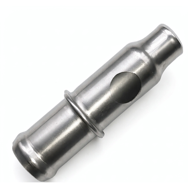
The Steel Deep Drawn Long Tube with Expanded Sections is an open-ended tube whose diameter is enlarged over part of its length – one or more bulges, bells or expanded bands between straight sections. The expanded region is what the part is for: it seats a seal, houses a component, or provides a shoulder that a straight tube cannot. The difficulty is that expanding a drawn tube is the opposite of drawing it – you are pushing wall outward, which thins the wall and, on a long tube, is very hard to do without pulling the whole length out of straight. This page works through the expansion method, the wall it costs and the straightness you have to protect along the way.
Expanding is the reverse of drawing, and the wall pays for it
Drawing pulls wall inward and the flange feeds material in; expanding pushes wall outward and there is no material feeding in, so the wall simply gets thinner as the diameter grows. The relationship is close to area conservation: the metal that used to cover the smaller circumference now has to cover a larger one, and it can only do that by stretching. On a long tube with an expanded band, the amount of thinning in that band is set by how much the diameter is grown and over what length.
- Thinning in the expanded section is predictable from the diameter increase, and we calculate the worst-case wall before we commit to the expansion ratio.
- We hold a minimum wall in the expanded region against the pressure or load the part has to carry, and we say so at quotation rather than discovering it at the press.
- Where the expansion is large, we discuss whether the expanded region should be a separate formed feature rather than an expanded tube, because beyond a certain ratio expanding stops being economical.
Choosing the expansion method: mandrel, swage, or segmented
There is more than one way to enlarge a tube, and the choice changes both the wall outcome and the tooling cost. A hard expanding mandrel or ball forces the whole band outward in one stroke and is fast but concentrates the stretch. A swaging or roller process works the band progressively and can hold wall better but needs more setup. A segmented internal tool opens like an umbrella and can form complex or stepped expansions. We pick per geometry.
- A single mandrel expansion is cheapest and fine for modest diameter growth over a short band.
- Progressive or roller expansion holds wall better and is chosen when the expansion ratio or the length of the band makes a single stroke too aggressive.
- The tube is always internally supported or the process is controlled so the expansion does not simply push the wall into an oval; a long tube expanded without support comes out egg-shaped.
Straightness over the whole length is the hidden specification
On a long tube the expanded band is only part of the problem; the rest of the length has to stay straight, and the expansion itself is one of the things most likely to bend it. Any unevenness in the expansion – one side of the band stretching more than the other – leaves the tube with a bow, and a bow in a long tube prevents it from seating into a mating bore no matter how good the expanded section is. Straightness is therefore a first-order requirement, not a nice-to-have.
- We support the tube along its length during expansion, because an unsupported long tube bends under the expansion force even when the tool is centred.
- Straightness is measured over the full length after expansion, on rollers or in v-blocks, not inferred from the ends.
- A final light sizing or straightening pass is scheduled when the part needs tight straightness, and we quote it as a defined operation rather than an informal fix.
Transitions and the shoulders the expanded section creates
The ends of the expanded band – where the enlarged diameter steps back down to the straight tube – are stress concentrators and the place the part is most likely to fail in service. A sharp step concentrates stress and is also a hard feature to form cleanly, because the metal has to change direction abruptly. We favour a blended transition where the design allows, and we control the shoulder geometry so the expanded section both forms well and survives load.
- Transition radius is specified where the part sees cyclic load, because a sharp shoulder at the end of an expanded band is a classic fatigue initiation site.
- The shoulder face itself – if the expanded band seats against something – is checked for squareness to the tube axis, since a cocked shoulder seats unevenly.
- Wall thickness at the transition is measured specifically, because the thinning is worst where the band steps back to the straight section.
How we verify a long tube with expanded sections
Verification on this part follows the length: the expanded band, the transitions and the straight sections in between are each checked against what the assembly needs.
- Straight sections: outside diameter and straightness over the full length measured after expansion, on rollers or v-blocks, because bow is the dominant defect on a long part.
- Expanded band: maximum diameter, length of the expanded region, and wall thickness at the thinnest point, measured against the calculated minimum.
- Transitions: shoulder squareness and the transition radius confirmed, with wall thickness checked where the band steps back to the straight section.
- Ovality in the expanded band measured, since an expanded tube that is not round will not seal or seat.
- Material certificate per lot, with the drawn-stock condition recorded so the expansion behaviour is traceable.
- Fit check on the first article: the tube is inserted into its mating assembly and the expanded section’s seating or seal engagement is confirmed before the run.
First articles and retention samples are kept for the programme, so a repeat order of the expanded tube is expanded from the same verified baseline. On a part whose value is entirely in a formed section along a long, bow-sensitive length, that baseline is what keeps the second batch seating as squarely as the first.
Draw ratio, wall thinning, radii and trim — the design decisions behind a part like this are worked through with numbers in our deep drawn covers guide, and the Precision Deep Drawn Parts pages collect the rest of the family.
Specifications
| Item | Steel Deep Drawn Long Tube with Expanded Sections |
|---|---|
| Brand | AUNOV |
| Designing | Send us your 2D drawing, or mail a tube sample for measurement, you get a DFM review together with the quotation. |
| Tooling | Every die designed and built in our toolroom, stored under your part number. |
| Samples | First-article samples ship with dimensional data and material certs. |
| Materials | Carbon steel (SPCC / DC01) leads the stock list for this part, alongside 304 / 316 stainless steel, aluminium, brass and copper, with grade selection confirmed at drawing review. |
| Surface finish | Surface treatment per the drawing: plating, e-coat, powder coating, anodising, passivation, per the drawing. |
| Processing | Staged deep drawing with in-line annealing where needed, then pierced and machined in house. |
| Equipment | Mechanical presses 5-250 T, hydraulic presses 250-500 T, CNC turning and milling cells, a climate-controlled CMM room. |
| Tolerance | +/-0.1 mm as-drawn, machined features held to +/-0.03 mm. |
| Delivery terms | FOB is standard; DDP offered for EU and US, T/T or L/C, with D/P for repeat business, call-off schedules supported. |
Frequently Asked Questions
Why does an expanded section always end up thinner than the tube it came from?
Expanding is drawing run backwards, and nothing feeds material in. Drawing pulls the wall inward while flange material flows to replace what moved; expanding pushes the wall outward with no supply, so the metal that covered the smaller circumference now has to cover a larger one. The result follows area conservation closely enough that thinning can be estimated from the diameter increase before tooling is cut, which makes it a design question rather than a surprise at first article.
Mandrel, swage or segmented tooling – how is the expansion method chosen?
By how much the diameter has to grow, how accurate the expanded band must be, and where it sits along the tube. A mandrel pushed or drawn through sets the bore directly, which suits a sealing band that has to match another part. Swaging forms against the outside and is fast for modest growth. Segmented tools expand from the inside out and cope with a larger change or several bands along one length. The shoulder each leaves behind and how much straightness each preserves are usually what decides it.
Why is straightness over the full length the requirement that gets missed?
Because it is invisible in a section drawing and rarely called out until the assembly jams. A drawn tube leaves the press reasonably straight, but expanding and any correction afterwards introduce bend, and the longer the tube the more a small deviation becomes misalignment at the far end. It therefore has to be specified over the full free length, with a datum scheme reflecting how the tube is supported, rather than stated per unit length.
How abrupt can the transition into an expanded section be?
Less abrupt than looks tidy on a drawing. The shoulder concentrates the change in diameter, so a near vertical step gathers stress, and it also gives a seal very little progressive surface to load against. A generous transition radius helps both forming and service life. Where the shoulder genuinely has to act as a stop or seal seat, perpendicularity of that face becomes its own callout instead of a consequence of the form.
Related Products



Request a Quote for This Part
Send a drawing or sketch — get material advice, tooling cost and a per-piece price within 24 hours (working days).