
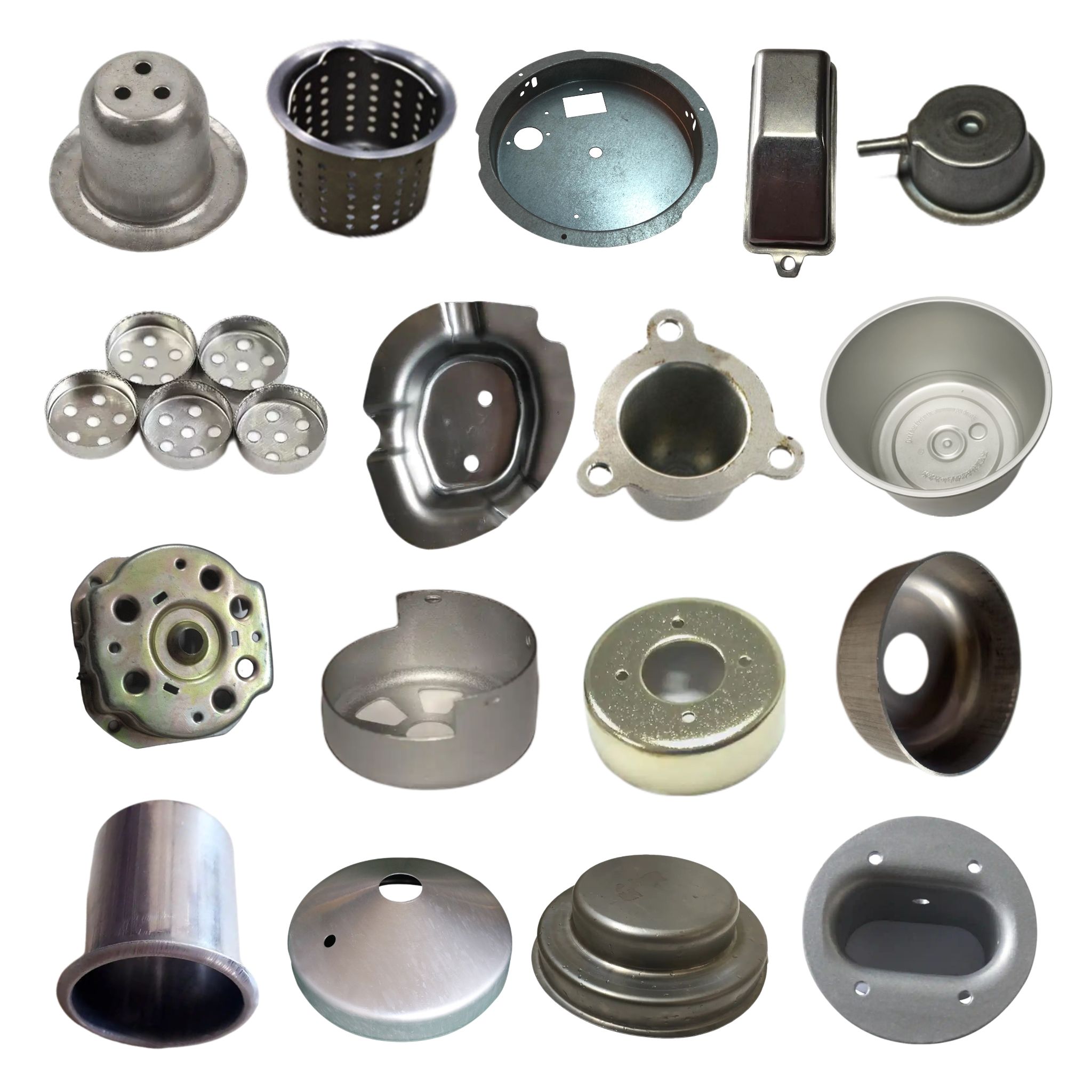
The Assorted Deep Drawn Cups and Vented Covers family puts two geometries on one release: solid cups that hold depth and a bottom, and vented covers whose job is to let something through while still shielding what is underneath. The engineering difference is larger than it looks. A cup is judged on its depth-to-diameter ratio and the wall it can hold at the bottom of the draw; a vented cover is judged on how much open area it can give away before it loses the stiffness it needs to stay flat and seal. Managing both on one shop floor means two process plans and one schedule, and this page is about where the two disciplines collide and how we keep them from cross-contaminating each other.
A cup is a depth problem, a vented cover is a stiffness problem
These two parts are drawn on the same presses but they fail for opposite reasons. A deep cup fails by tearing at the punch radius when it is drawn too far in too few stages, or by wrinkling in the flange when the holder pressure is too low. A vented cover is usually shallow, so tearing is rarely the risk; its risk is that the vent pattern removes so much material that the cover oil-cans, bows under fastener torque, or loses the flatness its gasket needs. The control plan therefore treats them as two products even when they ship in the same box.
- Depth-to-diameter ratio on the cups decides the number of draw stages; we set the stage plan before quoting, because adding a stage after tooling is cut is the expensive way to find out.
- Open-area ratio on the vented covers is a stiffness calculation first; we ask what the cover has to resist – bolt load, internal pressure, a person’s hand – before we cut the pattern.
- Shared presses, separate tooling: both may run on the same tonnage class, but the dies, holders and lubricants are set per part, and the setup sheet says so explicitly.
Sizing the vent pattern against the stiffness it removes
A vent pattern is a trade between how much air or fluid must pass and how much metal can be spared. The trap is treating the vented cover like a solid cover with holes in it. Every hole is a stress riser and a place where the flatness was doing its job. We lay the pattern out so the remaining material still forms a load path from fastener to fastener, and we check the cover’s deflection under the actual assembly torque before the pattern is released.
- Hole diameter relative to wall thickness sets the piercing limit: a hole much larger than the wall invites tearing and heavy burr, so very open patterns push us toward a different process than simple piercing.
- Open area is specified against a required flow, not against an aesthetic, and we confirm the customer’s flow number rather than guessing a percentage.
- Burr direction is set so it faces away from the sealed or handled side, because a burr on a vented cover is both a cut risk and a place for a gasket to fail.
Order of operations: pierce the vents before or after the draw
On a shallow cover it is tempting to pierce the vents in the flat blank and then draw. That is usually wrong: drawing after piercing pulls the holes out of position and distorts them, especially near the corners of a rectangular cover or the edge of a shallow draw. The reliable route is to draw the cover to shape first, then pierce the vents in the formed part in a secondary die that references the drawn flange as the datum.
- Piercing after forming holds hole position to the flange, which is what the assembly actually sees.
- Draw-then-pierce adds a die and a handling step, and we quote it openly rather than hiding the cost in the pattern.
- Where a customer insists on pierce-then-draw for cost, we run it on a trial blank first and show them the hole-position shift so the decision is made on data.
Keeping a shallow cover flat when the vents want it to bow
Flatness is the hidden specification on any cover, vented or not, because the cover has to clamp down against a gasket and the fastener torque will find any bow. Drawing a shallow part flat is its own discipline: too little holder pressure wrinkles the flange, too much draws the metal thin at the radius and sets up a springback bow once the part is released. On a vented cover the problem compounds, because removing material lets the remaining metal relax into a different shape after trimming.
- We measure flatness on a surface plate after trimming, not on the as-drawn part, because the trim releases stress and moves the flat.
- Stiffening features – a shallow bead, a rolled edge or a flange return – are proposed when the vent pattern has eaten the stiffness budget.
- Parts are stacked and supported in the packing so that shipping does not become the operation that dents the flat the customer needs.
How we verify cups and vented covers from one mixed release
Because the two geometries verify differently, the control plan carries both sets of criteria and the paperwork records which check applies to which part number:
- Cups: inside diameter, depth and bottom thickness measured per the control plan, with a draw-stage and holder-pressure record so any depth drift traces back to the press.
- Vented covers: vent hole size and position to the flange datum, open-area verification on the first article, and burr direction confirmed on both faces.
- Flatness on every cover checked on a surface plate after trim, against the number the gasket actually needs.
- Material and finish certificates per lot, with coating or passivation records attached to the release.
- Fit and function check on the first article: the cover is clamped to its mating surface with the production fastener torque and the gasket seating is inspected.
- Packing and count confirmed, with retention samples drawn from each geometry before the mixed lot is boxed.
The first articles and retention samples are kept as physical references for the run, so the next release starts from a measured baseline. On a family this mixed, that baseline is what keeps the cups from being judged as covers and the covers from being released as if they were solid.
Drawing a cover like this is a chain of decisions — draw ratio, wall thinning, radii and trim. Our deep drawn covers design guide works through each of them with worked numbers.
Specifications
| Item | Assorted Deep Drawn Cups and Vented Covers |
|---|---|
| Brand | AUNOV |
| Designing | A drawing file or a physical sample starts the review, DFM feedback is returned with the quote. |
| Tooling | Dies designed and built in our own toolroom, stored under your part number. |
| Samples | The first-article set ships with dimensional data plus material certs. |
| Materials | Carbon steel (SPCC / DC01), 304 / 316 stainless steel, aluminium, brass and copper are stocked, with grade selection confirmed at drawing review. |
| Surface finish | Surface treatment per the drawing: plating, e-coat, powder coating, anodising, passivation, per the drawing. |
| Processing | Staged deep drawing with in-line annealing where needed, then pierced and machined in house. |
| Equipment | Mechanical presses 5-250 T and hydraulic presses 250-500 T, CNC turning centres, climate-controlled CMM room. |
| Tolerance | Tolerances to +/-0.1 mm as drawn, +/-0.03 mm on machined surfaces. |
| Delivery terms | FOB standard, DDP offered for EU and US, payment T/T or L/C, D/P for repeat accounts, call-off schedules and blanket orders supported. |
Frequently Asked Questions
On a mixed release, which member gets proven first?
The one nearest its own limit, because these two geometries fail from opposite ends. The deepest cup is what proves the drawing ratio and the punch radius, since it sits closest to tearing. The widest, most heavily pierced cover is what proves flatness after venting, because removing material releases stress the forming put in. Sampling order therefore follows whichever member has least margin rather than whichever is most typical, and first articles are planned against that worst case.
Can one tolerance scheme usefully cover both geometry types?
Not really. The deep members need depth, wall distribution and height-controlled dimensions; the shallow covers need flatness, pattern position and edge condition. Writing one general tolerance block over both leaves each member’s actual controlling characteristic unstated, which turns inspection into argument instead of evidence. The workable arrangement is a shared general tolerance block plus specific callouts for whatever each member is judged on.
Can the cup and the cover share tooling?
Partly, and usually less than people expect. Sharing a press and a secondary line is straightforward, since both members are drawn, trimmed and pierced on similar equipment. Sharing a blank diameter or a first drawing stage only works when the first-stage reduction suits both shapes, which is uncommon when one member is deep and the other shallow. Sharing a piercing station depends entirely on whether the hole patterns can coexist, and in mixed families they generally cannot.
Besides open area, what else should the print say about the vent pattern?
Four things, all routinely missing. Ligament width between openings, which is what actually carries load across the pattern. Distance from the pattern to the trimmed edge, because that band is what keeps the remainder of the cover stiff. The datum the pattern is positioned from, which decides whether the vents line up with whatever sits behind them. And which side of the pierced holes may carry the burr, which matters as soon as the cover has to seat against something flat.
Related Products



Request a Quote for This Part
Send a drawing or sketch — get material advice, tooling cost and a per-piece price within 24 hours (working days).