
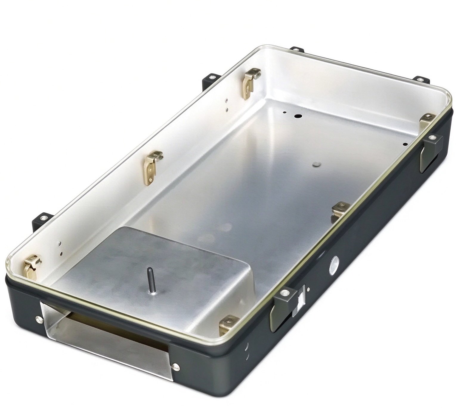
The Steel Deep Drawn Battery Tray with Mounting Rails is a formed pocket with two side rails that locate and bolt a battery or cell pack, and its job is structural: it has to hold the pack square, survive the rails being loaded in shear, and not sag under the pack weight. The engineering below is about forming the pocket and the rails in one strip and then holding the rail pitch so the pack actually seats.
Forming the tray pocket and the rail flange in one strip
A battery tray is drawn as a shallow pocket – typically 250 mm by 180 mm by 40 mm deep from 1.5 mm DC01 – with the two long sides turned up into rails rather than added as separate brackets. We form it in one strip so the rail and the pocket wall are one piece of steel, which removes the weld or clinch that would otherwise be the first thing to fail in shear. The pocket is drawn at about 30 percent reduction, and the rails are wiped up from the same draw in a follow-on station so the rail flange sits flat at 20 mm above the pocket floor.
The rail flange is where the pack bolts down, so it is wiped to a flat better than the pocket wall – we iron the flange in the last station to +/-0.2 mm flatness so the pack does not rock on the rail. The pocket floor is allowed +/-0.3 mm because it only supports the pack through its own stiffness, not through a bolting face.
- Pocket 250 x 180 x 40 mm from 1.5 mm DC01, drawn at ~30 percent.
- Rails wiped up from the same draw; flange ironed to +/-0.2 mm flat.
- Pocket floor allowed +/-0.3 mm; the rail flange is the precision face.
The strip is fed through the draw and the rail wipe in a single progressive die so the pocket and the rails are made in one hit, which is what guarantees the rails are square to the pocket by construction rather than by adjustment. We set the blank clamp high through the pocket draw and release it for the rail wipe, because clamping through the wipe would stretch the flange and throw the pitch; the sequenced clamp is the difference between a tray that seats and one that rocks.
Keeping the rail pitch so the pack seats square
The rail pitch – the distance between the two rail bolt lines – is the tray’s only true locating dimension, so it is held to +/-0.1 mm even though the tray is drawn. If the pitch drifts by 0.3 mm the pack binds or rocks, and on a battery that means a cell under clamp load it was not designed for. We hold the pitch by locating the rail wipe dies off a common centre rather than off each rail independently, so any thermal or wear drift moves both rails together and the pitch stays put.
Rail parallelism is held to 0.2 mm over the 250 mm length, measured on a CMM at first article and gauged in production with a calliper bridge that spans both rails. A tray that is out of parallel loads one rail in bending and that is where the flange cracks at the weld-nut.
- Locate both rail wipes off a common centre to hold pitch to +/-0.1 mm.
- Hold rail parallelism to 0.2 mm over the length; gauge with a calliper bridge.
- Treat pitch as a machined feature, not a drawn one.
Steel grade and coating for a battery tray
DC01 is the default for a tray because it draws the pocket cleanly and takes e-coat without prep drama. Where the tray sees the underbody or a wash bay we specify a zinc-coated base (Z140) or e-coat to 20 microns, because a battery tray rusts from the inside of the pocket first and a painted-only tray fails there. We avoid aluminium for trays that carry heavy packs because the rail flange needs the stiffness of 1.5 mm steel at the bolt line; aluminium would need to be thicker and heavier to match.
Coating thickness at the rail flange is controlled because the weld nuts sit there: too thick a coat and the nut stands proud and the pack will not seat; we hold the flange coat to 15 microns and mask the nut faces during e-coat so the threads stay clean. A nut with coating in its thread is a pack that will not bolt down.
- DC01 default; Z140 base or 20-micron e-coat for wet environments.
- Hold flange coat to 15 microns; mask weld-nut faces during e-coat.
- Avoid aluminium unless weight is free and stiffness is not needed.
Controlling tray depth and weld-nut position
The pocket depth sets how deep the pack sits, so it is held to +/-0.3 mm and the floor flatness to 0.5 mm so the pack base bears evenly. The weld nuts on the rail flange are projected and welded after forming, located to +/-0.1 mm from the rail centre line, because a nut that drifts 0.2 mm is a pack that will not line up with its own holes. We weld the nuts on a stud-welder with the tray located off the same common centre used for the rails, so nut position tracks rail pitch automatically.
Weld-nut pull-out is verified by a torque test on first article – we spec a minimum 8 Nm seating torque and test to 15 Nm without the nut lifting. A nut that lifts at 15 Nm is a nut that will spin in service when the pack is serviced, and that is a field failure we design out at the sample.
- Pocket depth +/-0.3 mm; floor flatness 0.5 mm.
- Weld nuts located +/-0.1 mm off the rail centre; torque-tested to 15 Nm.
- Weld nuts off the same common centre as the rails so position tracks pitch.
The weld-nut projection height is set to match the 1.5 mm stock so the nut seats flush and the weld splashes into the flange instead of proud of it; a nut that sits proud is a pack that will not bear on the flange and a thread that collects splash. We dress the weld tips on a hit count so the projection stays consistent, because a worn tip is the usual cause of a nut that lifts at the torque test.
Where a battery tray sags and how we stiffen it
A tray sags in two places: across the pocket floor under pack weight, and at the rail free ends where the pack overhangs. Floor sag we control by drawing the pocket with a shallow crown or a rib, formed into the floor in the same draw so it costs nothing extra; a 3 mm crown over the 180 mm width takes the pack weight without the floor oil-canning. Rail-end sag we control by extending the rail past the pack at both ends and adding a return flange, so the rail is supported at its tip instead of cantilevered.
The third real failure is a rail flange crack at the weld-nut, where the nut pulls the flange in bending. We open the flange fillet to 2 mm and keep the nut at least 12 mm off the flange edge so the load spreads; a nut hard against the edge is a flange that cracks on the first pack removal.
- Crown or rib the floor 3 mm to stop oil-canning under pack weight.
- Extend and return the rail ends so they are not cantilevered.
- Keep weld nuts 12 mm off the flange edge with a 2 mm fillet.
We confirm the stiffening on first article by loading the empty tray with a mass equal to the pack and measuring the floor deflection; anything over 0.5 mm at the centre is sent back to add a rib rather than shipped, because a tray that visibly sags in the sample will sag worse with the pack and a cell in compression it was not designed for.
How we verify a battery tray before it leaves the floor
A battery tray is verified at first article for the dimensions that matter – pitch, parallelism, nut position and weld strength – and then gauged lightly in production because the strip-formed process is stable once set.
- First article: CMM on rail pitch and parallelism, pocket depth and floor flatness, weld-nut position, plus an 15 Nm nut pull-out test and a material certificate.
- Production: calliper-bridge gauge on pitch and parallelism every run, nut-position pin check, and a torque audit on the first and last tray.
- Shipment file: dimensional report, nut pull-out record, coating thickness, and material cert travel under your part number.
The draw die, rail wipe and nut-weld fixture are built and held in our own toolroom against your part number, with the rail pitch archived off the common centre so a reorder reproduces the seat. A reorder is a strip run and a gauge pass, not a new tooling program.
Choosing between drawing, machining and welding comes down to the shape of the part: the guide to deep drawn covers sets out where each route wins, and the overview page links through to the full Precision Deep Drawn Parts range.
Specifications
| Item | Steel Deep Drawn Battery Tray with Mounting Rails |
|---|---|
| Brand | AUNOV |
| Designing | Send us your 2D drawing, or mail a sample for measurement, DFM feedback is returned with the quote. |
| Tooling | Every die designed and built in our toolroom, with your part number on the tool record. |
| Samples | Samples for approval come with a dimensional report plus material certs. |
| Materials | Carbon steel (SPCC / DC01) leads the stock list for this part, alongside 304 / 316 stainless steel, aluminium, brass and copper, with grade selection confirmed at drawing review. |
| Surface finish | Finishes on offer: plating, e-coat, powder coating, anodising or passivation, set by your print. |
| Processing | Progressive deep draw stages with in-line annealing as the draw ratio demands, then pierced and machined in house. |
| Equipment | Mechanical presses 5-250 T, hydraulic presses 250-500 T, CNC turning centres and a climate-controlled CMM room. |
| Tolerance | Expect +/-0.1 mm as drawn and +/-0.03 mm where surfaces are machined. |
| Delivery terms | Standard terms FOB, DDP offered to EU and US, T/T and L/C accepted, D/P for established customers, blanket orders and call-offs supported. |
Frequently Asked Questions
Why form the pocket and the mounting rails from one strip?
Because the alternative adds a joint. Rails fitted as separate brackets need a weld or a clinch, and that joint is the first thing to fail in shear. Forming pocket and rail as one piece of steel removes the joint and keeps grain continuity through the section that carries the load.
What flatness can you hold on the mounting rail flange?
The pack bolts to the flange, so the flange is ironed in the last station to +/-0.2 mm flatness and the pack does not rock on the rail. The pocket floor is allowed +/-0.3 mm, because it supports the pack through its own stiffness rather than through a bolting face.
Which steel and coating suits a battery tray?
A drawing steel such as DC01 suits the draw, with the coating chosen from the duty the tray sees. The environment decides whether bare, plated or painted is right, and the coating has to survive the forming sequence, not only the salt spray cabinet.
How do you stop a battery tray from sagging?
Sag is a stiffness problem solved with geometry. Rail pitch is held so the pack seats square, tray depth and weld-nut position are controlled through the forming stations, and where deflection still threatens the load path we look at the shape of the pocket before we add steel.
Related Products


Request a Quote for This Part
Send a drawing or sketch — get material advice, tooling cost and a per-piece price within 24 hours (working days).