
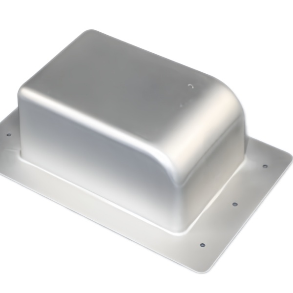
An aluminium dome cover with a flange base: why this geometry works
An aluminium deep drawn dome cover with flange base is a one-piece pressed shape – a domed top for stiffness, straight walls for depth and a flat flange at the open end for sealing and fastening – formed from a single aluminium sheet blank in one or two hits. The aluminium deep drawn dome cover with flange base is one of the most efficient shapes a press can make: a domed top for stiffness, straight walls for depth, and a flat flange at the open end for sealing and fastening. One drawing stroke produces all three. Compared with a machined billet cover, the drawn version typically lands at 30-60% of the weight and a fraction of the cost at volume, because the material is a 0.8-2 mm sheet blank rather than a solid block cut away.
The dome is not a styling choice. A flat cover over a wide span flexes and rattles; a domed skin resists bending the way an eggshell resists crushing. For enclosures over motors, gearboxes and electronics, the dome adds rigidity exactly where a flat panel would need pressed ribs – and ribs are precisely what deep drawing cannot do cleanly. The geometry and the process agree with each other, which is why this cover keeps winning designs away from fabricated alternatives.
Sizes and proportions we draw in aluminium
- Diameters 20-300 mm for round covers; oval and rectangular domed covers with generous corner radii are equally routine.
- Dome height 15-40% of diameter. Shallow domes draw in a single hit; deeper domes take a second station. Beyond about 45% the dome itself becomes the limiting feature and we will show you where a two-piece design or a deeper centre boss changes the economics.
- Wall 0.8-2.5 mm in the common aluminium grades; thicker walls need hot-formed or stamped alternatives and we will say so.
- Flange width typically 8-25 mm, flatness 0.3 mm per 100 mm as-drawn – or 0.1 mm coined, when the flange carries a gasket.
Mounting holes, vent bosses and cable slots are pierced after forming so their positions stay true; piercing them before the draw is the classic rookie error that leaves holes oval and positions wandering.
Choosing between 1050, 3003 and 5052 – the decision is about your load, not the price list
1050 is the softest and the cheapest, draws beautifully, and suits covers whose job is shielding and appearance – it dents if you lean on it. 3003 adds strength with only a small penalty in formability; it is the default for motor and gearbox covers that get handled. 5052 carries real structural load and resists vibration fatigue; it work-hardens faster, so deep domes may need an extra anneal or a wider die radius. If your cover bolts onto something that moves, start the conversation at 5052; if it shields something static, 1050 probably wins on cost.
Surface comes next. Mill finish suits painted or coated covers. For visible aluminium we draw with protected film and finish in anodising (natural or black, 5-15 µm film) or chemical conversion coating when the cover must stay conductive for earthing. Powder coating over aluminium is available through our audited partners with the same batch traceability as the metalwork.
The flange is where sealing is won or lost
A flange that looks flat on a drawing is rarely flat enough to seal after drawing – the drawing operation leaves a slight flare and memory of the die radius. Our standard answers:
- Coined flange face – a sizing stroke flattens the sealing band to 0.1 mm flatness; this is the choice for gasketed covers in wet or dusty environments.
- Beaded flange groove – a rolled bead formed in the flange captures an O-ring positively so assembly cannot pinch it out of position.
- Curled rim – for hand-exposed covers, the rim is curled to remove the sharp edge and double the rim stiffness.
Tell us the sealing method at RFQ (gasket, O-ring, gasket-less metal-to-metal) – the flange detailing is designed around it, and retrofitting a seal concept later costs a tooling change.
Tolerances, honestly stated
- Flange OD ±0.3 mm as-drawn; ±0.15 mm after a sizing pass.
- Overall height ±0.5 mm; dome apex thickness not below 80% of nominal wall.
- Flange flatness 0.3 mm/100 mm as-drawn, 0.1 mm coined.
- Pierced hole positions ±0.15 mm to drawing datums.
Machined features after drawing (spot-faced bosses, tapped holes) hold ±0.03 mm. First-article layouts report every drawing dimension with the measurement method named.
Where these covers are working
- Electric motor and gearbox nose covers in 3003, powder coated, with coined flanges for lip-seal mating.
- Outdoor sensor and antenna domes in 5052 with conversion coating under paint – the dome sheds water and resists wind load.
- Light-fitting and luminaire covers in 1050, anodised or painted, where appearance and thermal spread both matter.
- Compressor and pump end covers in 3003 with beaded O-ring grooves, drawn at tens of thousands per month.
Questions we are asked about aluminium dome covers
Will the anodising hide the draw marks?
Anodising amplifies surface, it does not hide it. For cosmetic anodised covers we draw with fine-polished dies and ship with the draw texture agreed on a signed sample – or the cover goes through a light levelling polish first. Agree the standard on a physical sample before volume; that is what the sample approval stage is for.
Can the dome carry a threaded boss or a cable gland hole?
Holes yes – pierced and deburred after drawing. Threaded bosses are usually better as a riveted or welded nut on the inside face; welding bosses onto 5-series aluminium needs the right filler and is done by our partners, not in-house, and we will quote it that way honestly.
How does tooling cost compare with a flat cover?
The dome adds one forming consideration, not a second die: for most sizes the tooling premium over a flat flange cover is modest and the unit price is near-identical. The quotation shows both so you can see the difference yourself.
The drawing, the volume, and what the box must carry
Send the drawing, annual volume, and the three facts that shape the design: what it covers, where it is mounted, and how it seals. You get back the die sequence, material recommendation with reasoning, and a unit price that shows what each tolerance level costs – before any tooling money is spent.
If you are comparing this part with a machined or welded alternative, the guide to deep drawn covers lays out where drawing wins, where it loses, and what it costs either way.
Specifications
| Item | Aluminum Deep Drawn Dome Cover with Flange Base |
|---|---|
| Brand | AUNOV |
| Designing | Share your print, or send a part to be measured, you get a DFM review together with the quotation. |
| Tooling | Our own toolroom designs and builds every die, each die held against your part number. |
| Samples | Pre-production samples of the base ship with a full dimensional report and material certification. |
| Materials | Aluminium leads the stock list for this part, alongside carbon steel (SPCC / DC01), 304 / 316 stainless steel, brass and copper, per the drawing. |
| Surface finish | Plating, e-coat, powder coating, anodising or passivation as the drawing calls out, fixed at the drawing review. |
| Processing | Staged deep drawing, with in-line annealing where the draw ratio requires, pierced and machined on the same floor. |
| Equipment | Press capacity from 5 to 500 T across mechanical and hydraulic lines, CNC cells plus a temperature-controlled CMM room. |
| Tolerance | Tolerances to +/-0.1 mm as drawn, machined features held to +/-0.03 mm. |
| Delivery terms | Prices FOB, with DDP for EU and US on request, T/T or L/C, D/P on repeat business, call-off schedules and blanket orders supported. |
Related Products


Request a Quote for This Part
Send a drawing or sketch — get material advice, tooling cost and a per-piece price within 24 hours (working days).