
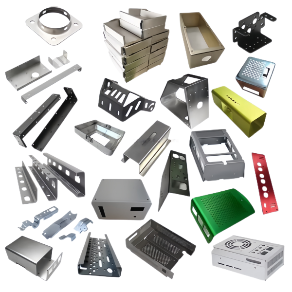
Brackets and chassis parts are the parts an assembly is built around – the bracket that locates a motor, the chassis that carries a board, the stiffener that stops a panel flexing. They are not difficult to form and they are easy to get subtly wrong, because the two things that decide whether they assemble are usually not on the drawing: the order the bends are made in, and which side the burr faces.
Bend order is a process decision the drawing has to allow
A bracket with two perpendicular bends and a return flange is bent largest radius first and the tight return last, because the tight bend needs the part already located against the first face. Reverse the order and the return pulls the first bend out of square. The drawing’s bend table also has to be reconciled against the minimum flange the tooling can form – a 6 mm flange called out on a press brake that can only form 8 mm is a quotation-stage problem, not a setup-stage one.
Grain direction decides whether a tight bend cracks
Bending with the grain on a 1.5 mm carbon steel bracket can crack the outside of a tight radius, while bending across it does not. We read grain direction off the stock certificate and clock the blank so tight bends run across the grain. This is invisible on the finished part and it is the difference between a bracket that survives installation and one that splits at the corner.
A burr on the wrong face throws the assembly off
Every cut edge on a stamped part has a burr on one side, and on a locating edge a tenth of a millimetre is enough to seat a motor off-axis in its bracket. We clock burr to the hidden side by default and note it on the setup sheet. Where parts stack, we deburr the stacking faces specifically and leave the others alone, because deburring everything costs time and can round an edge that was meant to stay sharp for a snap fit.
Chassis seams have to land where they can be reached
A chassis that is essentially a box section has to be welded or clinched somewhere, and the seam should land on a flat accessible face rather than in a corner. Planning that at the drawing stage costs nothing; discovering it at the fixture costs a redesign. Where a chassis will be plated, the seam position also decides whether the finish covers it.
How the lot is held consistent
Because these arrive as a mixed lot, bend order, burr direction and any coating are recorded per part on a setup sheet, so a reorder is made the same way round rather than re-derived. On parts whose fit depends on two things the drawing does not state, that is what keeps the second batch assembling like the first.
First articles are kept for the programme, and the setup sheet travels with the part number. On unglamorous parts that hold an assembly together, that is what makes a reorder a reorder.
This part belongs to our Metal Stamping range, where the tooling notes and forming practice behind the whole family are collected.
Where this part is used
Brackets and chassis parts are what an assembly is built around: the bracket that locates a motor, the chassis that carries a board, the stiffener that stops a panel flexing under load or vibration. We supply them into automotive and commercial-vehicle builds, into enclosure and cabinet work, and into OEM equipment where the same bracket appears in every unit. They are not difficult to form, which is exactly why they are easy to get subtly wrong.
The failures we see are almost never about strength. They are about bend sequence, grain direction relative to a tight bend, a burr on the face that has to sit flat, and a seam that lands where a hand or a tool cannot reach it.
What we need to quote it
Send the drawing with the bend sequence marked if your assembly constrains it, plus the material and thickness and which face is cosmetic. Tell us whether the bracket locates a component or only carries load, because a locating bracket needs the holes held to a datum while a load-carrying one does not. If the part is a replacement, a sample to measure is faster than a drawing.
Specifications
| Item | Assorted Stamped Brackets and Sheet Metal Chassis Parts |
|---|---|
| Brand | AUNOV |
| Designing | Send the drawing, or a sample we can measure, DFM feedback is returned with the quote. |
| Tooling | Our own toolroom designs and builds every die, held under your part number. |
| Samples | First-article samples of the part ship with dimensional data plus material certs. |
| Materials | The stock list runs carbon steel (SPCC / DC01), 304 / 316 stainless steel, aluminium, brass and copper, with grade selection confirmed at drawing review. |
| Surface finish | Finish options: plating, e-coat, powder coating, anodising or passivation, per your print. |
| Processing | Progressive deep draw stages with in-line annealing as the draw ratio demands, pierced and machined on the same floor. |
| Equipment | Presses run 5-250 T mechanical and 250-500 T hydraulic, with CNC turning centres and a climate-controlled CMM room for inspection. |
| Tolerance | +/-0.1 mm as-drawn, with machined features to +/-0.03 mm. |
| Delivery terms | FOB standard, DDP offered for EU and US, T/T and L/C; D/P on repeat accounts, call-off scheduling supported. |
Frequently Asked Questions
Why does bend order belong on the drawing rather than in the shop?
Because not every sequence is physically possible. Once one flange is formed it can block the tool from reaching the next bend, so the order decides what tooling can be used and therefore what the part costs. Leaving it open usually means someone discovers the restriction at the press, which is the most expensive place to discover anything.
How much does grain direction really matter on a tight bend?
Enough to decide between a part and a cracked one. Rolled sheet is directional, and bending across the grain in a tight radius can open cracks along the outside of the bend. Blank orientation is therefore a process setting rather than whatever nests best on the sheet, which is why it gets agreed before quoting.
Why is burr direction bracket that few people specify?
A burr on the wrong face holds the assembly apart. It occupies real space at the mating line, so parts that should sit flush appear to have a gap, and tightening does not close it because metal is in the way. Naming the face costs nothing on the drawing and removes a fault that is otherwise blamed on flatness.
Where should a chassis seam go?
Where someone can actually work on it. Seams get welded, sealed and inspected, and if the chosen location is buried inside the assembly none of the three can be done properly. Deciding seam position alongside the rest of the geometry avoids finishing homework nobody budgeted for.
Related Products


Request a Quote for This Part
Send a drawing or sketch — get material advice, tooling cost and a per-piece price within 24 hours (working days).