
An open flange is a decision about how the part mates, and it is a cheap decision to make wrong
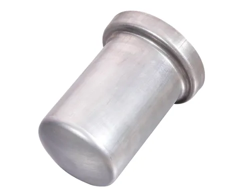
A deep drawn aluminium cable can with an open flange is a small cylindrical can whose rim is not closed but left open with a flange. That single word – open – carries most of the part’s design, because an open flange is a decision about how the can connects to whatever it holds, and each of the four or five ways to connect it gives a different requirement on the flange’s geometry. It is also a decision that is very easy to leave vague on a drawing and very expensive to change once the mating part exists.
We deep draw from coil or blank with in-process annealing so walls thin evenly, with in-process checks between stages, on mechanical presses from 5 to 250 T and hydraulic presses 250-500 T with in-line annealing furnaces, secondary operations on CNC turning centres, and CMM inspection. Flange and rim dimensions to +/-0.05 mm with the wall controlled by the draw, and capability is checked on the first article before the run continues. The material is 1050, 3003, 5052 or 6061 aluminium in 0.5-3.0 mm stock, with the temper matched to the forming depth or machining route of this can. Plating, coating or polishing to suit the drawing, with alternatives quoted with the quotation and samples approved in writing. This page is about the four ways to close an open flange, and what each demands of the drawing.
Why leave the flange open at all
An open flange is chosen for a specific reason, and the reason determines the geometry. Four common ones:
- It welds to a mating part. The flange is a welding land, and the weld is what makes the joint. This requires a flange that is flat enough to weld and wide enough to run a weld on, and it means the flange’s geometry is dictated by the weld’s requirements – bead size, position, access.
- It crimps onto a mating part. The flange is a crimp lip, and the mating part’s spigot or tube is deformed over it. This requires a flange that is thin, of a defined thickness and hardness, and formed to a specific diameter. It is a very common arrangement for cable cans, covers and end caps.
- It is a clearance or locating flange. The can drops into a hole and the flange locates it axially, and the can is retained by something else. This requires a flange with tight axial position tolerance and enough flatness to seat.
- It slides into a slot or rail. The flange is a mounting feature for a panel or a DIN-style mounting, which requires a specific flange shape and a specific thickness range.
Each connection method, and what it demands
| Welded flange | Flat and parallel to the can’s axis, wide enough for the weld’s bead and the torch or laser’s access, with a clean uncoated surface at the weld land. Any coating must be masked. The flange’s thickness has to suit the weld process, because a very thin flange distorts under a weld’s heat and a thick one needs more energy. |
|---|---|
| Crimp lip | Of a defined thickness – and this is a case where the flange’s thickness is a functional specification rather than a material thickness. The flange’s diameter, its thickness and the material’s hardness together determine the crimp’s grip and its fatigue life. A flange that is too soft will deform on assembly; too hard and the mating part cracks. |
| Locating flange | Held to the tight band of +/-0.05 mm, and its flatness measured against a named surface. The flange’s axial position sets the can’s location, so a variation here becomes a variation in whatever the can positions. This is a true position requirement from the can’s axis. |
| Panel or rail mount | Shape and thickness both functional, and the thickness range is often the tightest requirement on a small drawn part – a panel mounting clip has to fit a specific sheet thickness range and nothing else. |
The practical consequence: the drawing must state the connection method, because the same nominal flange geometry with a 0.3 mm wall and a 1.0 mm wall are two different parts for three of these four methods, and a customer who says “open flange” without saying what it connects to has not specified the part.
Flange and rim dimensions, and what the tight band should cover
Flange and rim dimensions to +/-0.05 mm is the right place for the tight band on this part, and there are three features that deserve it:
- The flange’s diameter or width, to its mating part, since this is the fit.
- The flange’s axial position, from the can’s end face, since this is what locates the can in its assembly.
- The flange’s flatness, against a named surface. A flange that is dished will not seat flat, and on a crimp or weld land a dished flange produces an inconsistent joint.
A drawn wall’s specification is really a material specification
The wall is controlled by the draw, which is an honest statement of the process and has real consequences for this part:
- The wall’s specification is a material specification. A drawn wall’s thickness is the incoming blank’s thickness, modified by the draw, and no machining step tightens it. So the wall’s tolerance is a purchasing requirement, and where the wall is functional – a crimp lip, a weld land, a pressure boundary – the material has to be bought to a thickness specification rather than to a grade.
- The wall thins toward the can’s depth, and the minimum is at the punch nose. On a crimp lip at the can’s open end, the wall is at its most drawn and least uniform, and the crimp’s thickness tolerance is set there.
- Corner and edge thinning at the flange’s root is where a drawn can’s wall is most stressed – the flange is where the load from a crimp or a weld enters the can. A stress concentration at the flange’s root and a locally thinned wall there is the combination that produces a crack at the flange, which is the most common failure on this part type.
Aluminium, and the four grades
1050, 3003, 5052 or 6061 in 0.5-3.0 mm stock, with the temper matched to the forming depth or machining route of this can. The four are genuinely different for this part:
- 1050 – the most ductile and the best surface finish. The right choice for a crimp lip, because a soft flange deforms correctly on assembly, and for a shallow draw.
- 3003 – slightly stronger, still very formable, the general-purpose choice and the most common for a drawn can.
- 5052 – considerably stronger with good corrosion resistance. Chosen where the can carries a load or where corrosion matters, and it draws less cleanly and takes a less even surface.
- 6061 – the machinability grade, chosen where the can has significant CNC finishing. Its draw formability is the poorest of the four, so a deep can in 6061 is a harder draw than the same can in 3003.
Anodising, and the flange is the problem
Plating, coating or polishing to suit the drawing. On an aluminium can, anodising is the natural finish and it has one specific problem on this part type: the flange.
- A crimp lip must not be anodised. Anodising hardens the surface and adds a layer that makes the crimp behave differently – and an anodised flange will crack or flake at the crimp rather than deform. The flange must be masked, and masking a flange is a real per-part operation on a small can.
- A weld land must be masked, because a coating at a weld either burns off, contaminates the weld, or causes porosity.
- A locating flange can usually be anodised, since the layer is thin and it only changes the dimension slightly – but the dimension has to be specified as post-anodise, and a locating flange that is anodised is harder to assemble than one that is not.
- The can’s body is where anodising earns its place – it gives a hard, cleanable, corrosion-resistant surface with negligible dimensional change, which on a cable can is exactly what is wanted.
A closed draw will not carry that load
Seven things, and the first is the one that resolves everything else:
- What the flange connects to, and how – welded, crimped, located, or a panel mount. This is the requirement the drawing is missing if it says only “open flange”.
- Flange diameter or width, and axial position, to the tight band, with the flange’s flatness called out separately.
- Flange thickness, where it is a crimp lip or a weld land, as a functional specification rather than a material note.
- Wall thickness at the flange root, and the minimum wall overall – because the flange root is where a drawn can fails.
- The mating part’s dimensions, or at minimum its critical ones, since the joint is a fit between two parts.
- Which surfaces are masked – the flange, almost always, and any thread or bearing feature.
- Material grade and temper, confirmed in writing, since the temper determines how the flange behaves on assembly.
Why is the flange open at all?
Why is the flange open at all? If the can is a cover or an end cap, a closed drawn rim with a bead is often stronger, needs no flange connection, and is cheaper to make. An open flange is the right answer when it must connect to something, when the connection needs to be serviceable, or when the design’s geometry requires a welding land. Stating the reason at enquiry stage prevents an open flange being specified by default and then having to be designed around.
Drawing, machining and welding each win on different geometries; the guide to deep drawn covers works through those boundaries, and the full Precision Deep Drawn Parts range is reachable from the overview page.
Specifications
| Item | Deep Drawn Aluminum Cable Can |
|---|---|
| Brand | AUNOV |
| Designing | Driven by your drawing or a physical sample – DFM notes are returned before any tooling is cut; revisions are re-quoted once rather than silently absorbed. |
| Tooling | Die design and toolmaking stay in house, so a die can be re-cut against the approved drawing, and the die remains dedicated to your part. |
| Samples | Sample parts are measured and reported before submission, so any deviation is corrected at sample stage. |
| Materials | 1050 / 3003 / 5052 / 6061 aluminium, 0.5-3.0 mm stock – temper matched to the forming depth or machining route of this can. |
| Surface finish | Plating, coating or polishing to suit the drawing; alternatives quoted with the quotation, samples approved in writing. |
| Processing | Deep drawing from coil or blank, with in-process annealing so walls thin evenly; in-process checks sit between stages, not only at the end. |
| Equipment | Mechanical presses from 5 to 250 T and hydraulic presses 250-500 T, with in-line annealing furnaces; secondary ops run on CNC turning centres, inspection on the CMM. |
| Tolerance | +/-0.05 mm on flange and rim dimensions, wall controlled by the draw; capability is checked on the first article before the run continues. |
| Delivery terms | Standard terms FOB; DDP available for EU and US, with T/T and L/C accepted. |
Frequently Asked Questions
Why does an open flange carry most of the design of a cable can?
An open flange decides how the can mates to whatever it holds, and each connection method – weld, crimp, press-fit or seal – demands different flange geometry. Leaving it vague on the drawing is cheap to specify and expensive to correct once the mating part exists.
Which aluminium grades are used for a drawn cable can?
1050, 3003, 5052 or 6061 aluminium with the temper matched to the forming depth or the machining route. Flange and rim dimensions are held to +/-0.05 mm, with the wall controlled by the draw.
Why is anodising a problem on the flange?
The open flange is the mating and sealing surface, and anodise build-up changes the rim dimension, so the flange band is controlled and measured after finishing rather than only before it.
How is a cable can quoted and verified?
Capability is checked on the first article before the run continues, and CMM data travels with the shipment. The typical minimum order is 1,000 pieces with a 24-hour quotation.
Related Products


Request a Quote for This Part
Send a drawing or sketch — get material advice, tooling cost and a per-piece price within 24 hours (working days).