
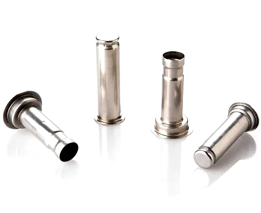
Four sleeves that have to work as one part number
A stainless steel flanged sleeve fittings set is a group of drawn tubular parts supplied against one drawing: each member is a round sleeve with a flange at one end, and they differ in length, step or end condition so each takes a different place in the same assembly. The important consequence is that it is a set rather than four convenient sizes — it is made together, sold together and expected to fit the same housing on the same day.
This pattern appears wherever one assembly needs the same interface repeated with variations — fluid or air manifolds, multi-port housings, filter and valve bodies, and equipment where several tubes leave the same face at different lengths. Buying them as one part number rather than four line items is what keeps the set consistent: one material lot, one heat treatment, one finish, and one gauging standard across every member.
Making them as drawn parts in stainless steel rather than cutting them from bar buys two things. There is no longitudinal seam, so there is no weld to inspect and no seam to finish, and the grain runs with the wall instead of across it, which is what the flange-to-tube junction needs when it is loaded. What it costs is that each member is a small project in itself, because the draw does not scale with length.
Seamless is the point worth dwelling on. A sleeve built from tube carries a join along its length that has to be dressed, inspected and trusted, and if it is welded, the heat-affected zone sits exactly where the flange-to-tube junction will be loaded. Drawing removes that entirely, which is why a set like this is worth specifying as drawn rather than fabricated even where a fabricated version looks cheaper per piece.
The flange is a datum, not a collar
Every sleeve in this family is located by what its flange does. The flange face is the surface that stops the part going further into the housing, and frequently the surface that clamps against a gasket or a shoulder, so its size matters less than its relationship to the tube axis. A flange that measures correctly but is not square to the bore seats on its edge rather than its face, and the sleeve then rocks under clamp load even though every dimension on the drawing was met.
The correct way to state that is a perpendicularity callout against the bore rather than a size tolerance alone. It is also why the corner between flange and tube stays radiused: that junction is where the set is most likely to be asked to carry load, and a sharp inside corner would put a stress raiser in exactly the wrong place.
Flange thickness matters for a different reason than people expect. It is rarely the flange that bends under clamp load; it is the tube just behind it, and how far that step sits from the flange decides whether it can. Where the load is high, material is left at the junction rather than added to the flange itself, which spends weight everywhere and fixes nothing at the place that needs it.
Steps and necked sections change the process, not just the drawing
Several members of a set carry a step or a reduced length somewhere along the tube. A step can be formed in the die or produced afterwards by machining, and the choice decides both cost and consistency. Forming it is cheaper per piece but needs room in the tooling plan, and there is a limit to how sharp a shoulder the metal will fill. Machining gives a crisp step and a controlled diameter at the cost of an extra operation and of exposing fresh material.
What usually decides it is volume and how tightly the step diameter has to be held. The honest answer is that some steps on a set are formed and some are machined, and it is settled per feature at review rather than by a house rule.
A step usually exists for one of three reasons: to give a press fit its stop, to let one diameter slide while another grips, or to form a lead-in so the sleeve enters its bore without shaving material off a seal. Each puts its requirements on a different feature, so a step drawn on a drawing is not a complete instruction — the diameter, the length and how square the shoulder has to be all need to be there.
There is also a limit to what forming alone will deliver. A step with very little difference between its diameters, or one that must sit within a tight length, generally wants machining, and forcing it into the draw produces a shoulder that varies more between pieces than between drawings. Where consistency across a set matters more than the cost of the operation, machining is the answer.
Drawing the set: why each size gets its own schedule
These pieces look like variations on one theme, and they are not. A longer sleeve needs more stages than a shorter one even at the same diameter, because each stage can only take a limited reduction before the wall gives up. The set is therefore planned as several short schedules sharing one material lot and one tooling philosophy, not as a single schedule stretched to cover four lengths.
Wall behaviour differs between members for the same reason. Where the wall has to meet a tolerance, the surface that needs it is brought back by turning and everything else is left as drawn, because stating the whole sleeve to a machined class costs money without adding function.
What genuinely is shared between members is everything except the draw itself: material lot, lubrication regime, anneal cycle and inspection plan. What cannot be shared is the number of stages, because that follows the reduction each member has to take. Annealing follows the same logic — whether a member needs an intermediate anneal depends on the total reduction it takes, so one member of a set can need relief while its neighbours do not. When that happens it is planned into the stage table and quoted openly rather than discovered after the first member splits.
Reading the four members: length, step and end condition each cost something
A set like this looks like one part photographed four times, and the differences between members are exactly where the cost sits. The longest member governs the stage count, and once it needs a stage the others do not, that stage becomes a tooling decision rather than a scheduling one. A stepped member needs either a second forming step or a machining operation, and which is chosen depends on how sharp the shoulder has to be. A closed-end member finishes differently from an open one, so its final operation cannot share the trim die its neighbours use.
None of this is an argument for simplifying the set — these members differ because the assembly needs them to. It is an argument for settling those differences at review rather than discovering them when the first set is being assembled and one member arrives short of reaching its seat.
Open, closed and stepped ends have to be stated
A drawn sleeve can finish open, closed at one end, or stepped to receive another part, and a set frequently contains more than one of those. Which condition each member has cannot be inferred from whichever is easier to make, because a closed end and a trimmed open end need different final operations and behave differently once installed. Where an end has to stay closed, the base is left at full thickness by the draw, which also makes it the end best suited to take any identification.
Open ends are trimmed, and where something has to slide over them the edge condition becomes part of the drawing: deburred and radiused if another part crosses it, square if it seats against a shoulder. A set frequently specifies more than one edge condition across its members, which is easy to accommodate provided it is written down rather than assumed.
Holding one standard across a reorder
A set is used together, so inconsistency between members surfaces at the assembly line rather than in inspection. Tooling is quoted once and held, the approved sample is retained as the master, and later batches are gauged back to it, with press and anneal settings recorded against the part number. That is what lets a reorder be priced on the part rather than on developing it again.
Material identity travels with the set as well: certificates and heat numbers accompany the first article, and the finish is selected from the drawing, with masking or marking where one member has to be told apart from its neighbours in the same carton.
Two things are worth deciding at enquiry, because they are expensive to change later. Whether the whole sleeve needs holding to a machined class or only the surfaces the assembly touches — usually the difference between a drawn price and a machined one — and how the members are to be identified, because a set whose pieces look alike in a carton is a set that gets mixed up on the line.
Whether a sleeve like this is drawn, turned from bar or built up from tube is decided by volume and by the wall it has to hold; the full Precision Deep Drawn Parts range is reachable from the overview page.
Specifications
| Item | Stainless Steel Flanged Sleeve Fittings, Four-Piece Set |
|---|---|
| Brand | AUNOV |
| Designing | Your drawing sets the part – samples are reverse-measured into a controlled drawing; revisions are re-quoted once rather than silently absorbed. |
| Tooling | Dies, fixtures and gauges are made in our own toolroom, so no tooling step is outsourced, and ownership is confirmed on the quotation. |
| Samples | Prototype and pre-production samples are provided against the drawing, so the sample is retained as the master, and later batches are gauged back to the signed sample. |
| Materials | Stock runs to carbon steel, 304 / 316 stainless steel, aluminium and brass; special grades are sourced to the drawing when volumes justify. |
| Surface finish | Plating, coating or polishing to suit the drawing; masking and laser marking available where needed. |
| Processing | Deep drawing from coil or blank, with in-process annealing so walls thin evenly; first articles verify the whole flow before the run is released. |
| Equipment | Mechanical presses from 5 to 250 T and hydraulic presses 250-500 T, with in-line annealing furnaces, backed by CNC turning centres and a climate-controlled inspection room. |
| Tolerance | +/-0.05 mm on drawn diameters, tighter bands confirmed against the drawing; critical dimensions carry CMM data with the shipment. |
| Delivery terms | Terms are FOB by default, with CIF and DDP quoted on request and freight priced to your door. |
Frequently Asked Questions
Do all four pieces follow the same draw schedule?
No, and pretending otherwise is what causes the trouble. Each stage can only take a limited reduction, so a longer member needs more stages than a short one of the same diameter. The set is planned as several short schedules sharing one material lot rather than one schedule stretched across all four.
Why does the flange need a perpendicularity callout rather than just a size?
Because the flange face is what stops and clamps the sleeve, so its angle to the bore decides how it seats. A flange can be correct in size and unsquare to the axis, and it will then bear on its edge and rock under clamp load instead of seating on its face.
Is the step formed or machined?
Either, depending on how sharp and how tightly held it has to be. Forming is cheaper per piece but limited in shoulder sharpness, while machining gives a crisp step and a controlled diameter at the cost of an extra operation. It is decided per feature at review, and a mixed set is common.
How do you keep a reorder matching the original set?
The approved sample is retained as the master and later batches are gauged back to it, with press and anneal settings recorded against the part number. Tooling is quoted once and held, so a reorder is priced on the part rather than on a second development.
Related Products

Request a Quote for This Part
Send a drawing or sketch — get material advice, tooling cost and a per-piece price within 24 hours (working days).