
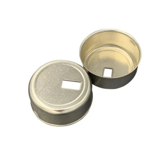
Deep drawn components: one forming process, a whole product family
Most sourcing engineers do not buy “deep drawing” – they buy a component: a housing that must seal, a cover that must align, a shell that must survive a press-fit, a can that must hold vacuum. This page explains how we take a component from a customer drawing to a running batch, and which decisions along that path decide whether the part is merely acceptable or genuinely right for the process.
The deep drawn components we ship fall into a handful of recurring geometries – cylindrical cans and shells, square and rectangular housings, covers with flanges, tubes and sleeves, drawn brackets. The differences between a good and a bad sourcing outcome rarely come from the geometry itself. They come from tolerance allocation, material selection, and how early the forming engineer gets to see the drawing.
How a component goes from drawing to running batch
Step 1 – Manufacturability review. Every RFQ gets a forming review before a price: draw ratio per axis, corner radii against wall thickness, hole-to-form distances, and where tolerances stack across your assembly. If a feature will fight the process – a hole 2 mm from a bend, a radius sharper than the metal allows – we flag it with a specific alternative, not a generic “please revise”. This review typically turns around inside 48 hours.
Step 2 – Tooling proposal. You receive the die sequence: how many stations, which operations in which order, and where annealing sits if the material needs it. Tooling is designed and built in our own toolroom, cut on CNC with wire EDM profile work, and held under your part number for the life of the program.
Step 3 – First article. Samples ship with a dimensional report laid out against your drawing: every dimension, measured, with the method noted. For automotive programs we run the full PPAP package on request.
Step 4 – Production. SPC on agreed key characteristics; certificates EN 10204 3.1; batches packed to your line-side specification. Because drawing, machining and measurement happen in one plant – including a climate-controlled CMM room – a dimension dispute never involves two factories arguing about whose gauge is right.
Tolerance allocation: the conversation that saves the most money
The single biggest cost lever on a drawn component is not the material or the press – it is which dimensions you make critical. A housing with a ±0.02 mm bore for a bearing press-fit needs a machining operation after drawing; the same housing with the bearing seat moved to a machined insert or the tolerance relaxed to ±0.05 mm with a sizing pass can skip that operation entirely. Neither answer is wrong, but the decision should be made with forming knowledge on the table.
Typical capability on our components: ±0.10 mm as-drawn on formed dimensions, ±0.05 mm after sizing or ironing, ±0.03 mm on machined features, flatness 0.1 mm on coined flange faces. When a drawing asks for better, we quote the extra operation explicitly – our quotations show the process route, so tightening one dimension shows up as one added line, not a mystery surcharge.
Material guidance by component role
- Sealed housings (electronic, sensor, actuator): 304 stainless steel or SPCC with e-coat. If the housing gets welded to a mating part after delivery, tell us – weld-grade 304 with controlled sulfur range behaves very differently from standard 304 at the seam.
- Conductive and RF components (shielding cans, contact shells): phosphor bronze, brass, or aluminium with chromate. Drawn shielding cans keep a continuous conductive path – no seam – which is why they outperform folded-and-welded shields in demanding RF work.
- Fluid-wetted parts (filter bodies, valve shells): 316L with passivation per ASTM A967, wall ironed for uniform flow area.
- Structural drawn brackets and reinforcements: HSLA or 5052-H32 aluminium, where the work hardening from drawing itself adds strength the flat sheet does not have.
Secondary operations under one roof
A component is rarely finished when it leaves the press. In-house we run: CNC turning and milling for bores, seal faces and threaded features; piercing and coining in-die; surface treatments – zinc plating, e-coat, powder coating, anodising, passivation – through audited partners we have used for years; and assembly operations where a drawn shell is joined to a machined insert or a stamped lid. Consolidating these under one PO is usually worth 10-15% against splitting them across vendors, mostly in logistics and re-inspection, and it puts one quality system behind the finished part.
Verification follows the component’s function, not a fixed checklist
Verification is matched to the component’s function, not a fixed checklist. A sealing housing gets flange flatness and surface-finish checks; a press-fit shell gets geometric roundness measurement and SPC on the fit diameter; an RF can gets conductivity-relevant plating thickness checks by X-ray. Samples for destructive checks (wall thickness profile, hardness, grain flow on request) are pulled per AQL or per your control plan. Every shipment carries inspection records traceable to the heat number.
Where this component family is used
- Automotive: actuator and motor housings, sensor shells, relay cans, seat-belt retractor parts – at line rates from thousands to hundreds of thousands per month.
- Industrial controls: enclosure shells, solenoid armatures, switch gear components.
- Medical and laboratory: instrument shells and centrifuge components in 316L, cleaned and packed to specification.
- Consumer and appliance: trim components, hinge barrels, drawn hardware where appearance surfaces are polished in-die.
Questions we are asked about custom drawn components
Can you work from a competitor’s part as a sample?
Yes. We reverse-measure the sample into a controlled drawing, you approve it, and tooling starts from there. The drawing is yours – which matters when you want the ability to move production later.
What volumes make deep drawing worthwhile?
For most component geometries the tooling pays back somewhere between 2,000 and 10,000 pieces a year depending on complexity. Below that we will say so and suggest a fabrication route; above it, unit prices fall steeply with volume and the part quality is more consistent than any welded alternative.
How do you protect our drawings?
Drawings and 3D data are stored access-controlled, tooling is under your part number in our toolroom, and we sign your NDA as standard practice – not as a favour to negotiate.
What we need before quoting a motor end cover
Send the drawing or sample, target volume, and the environment the component must survive. You get back a quotation with the forming sequence, tolerance capability against your print, and any design suggestions worth money – before you commit to tooling.
Not sure whether to draw, machine or weld this geometry? The guide to deep drawn covers compares the three routes and shows where each one wins; the full Precision Deep Drawn Parts range is linked from the overview page.
Specifications
| Item | Deep drawn components |
|---|---|
| Brand | AUNOV |
| Designing | Quotation follows the print, not a catalogue – unusual walls, threads or tolerances are feasibility-checked first; the approved drawing is kept as the controlled master. |
| Tooling | Die design and toolmaking stay in house, so die cost stays transparent, and the die remains dedicated to your part. |
| Samples | Samples are issued for approval before the run, so the part is proven before it is made in volume, and mass production is gated on that approval. |
| Materials | Carbon steel (SPCC / DC01), 304 / 316 stainless steel, aluminium and brass are held on site; material substitutes are proposed only with your written approval. |
| Surface finish | Plating, powder coating, anodising or polishing, per the print; the agreed finish travels with the part number. |
| Processing | Deep drawing on maintained presses, blank size and lubrication logged per run; in-process checks sit between stages, not only at the end. |
| Equipment | Mechanical presses 5-250 T plus 250-500 T hydraulics, with in-line annealing, with CNC turning centres for secondary operations and CMM inspection. |
| Tolerance | +/-0.05 mm on formed features, with capability data on critical dimensions; dimensional reports accompany the first article. |
| Delivery terms | FOB, with DDP offered for EU and US addresses, T/T or L/C, with D/P accepted on repeat business; repeat orders reuse the approved first article. |
Related Products


Request a Quote for This Part
Send a drawing or sketch — get material advice, tooling cost and a per-piece price within 24 hours (working days).