
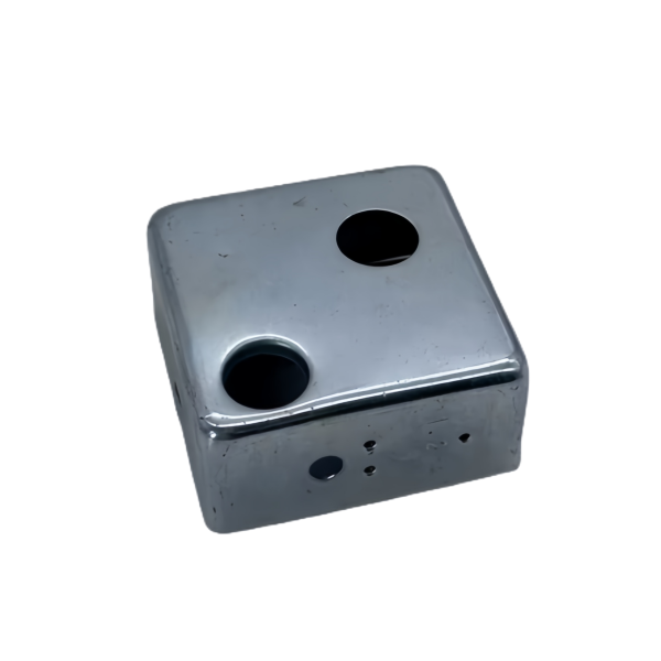
The Steel Deep Drawn Cubic Box with Dual Side Holes is a closed box shell – drawn as a square or rectangular cup – with a hole pierced through each of two opposite side walls. The box carries the usual square-draw difficulty in its four corners, but the feature that drives the engineering is the pair of side holes: they are pierced into walls that have already been formed and thinned by the draw, they have to line up across the box so whatever passes through one exits the other square to the axis, and they turn a stiff closed box into one with two large openings in its most load-carrying walls. This page covers the cubic draw, the paired side holes and the alignment between them.
A cubic box draws as four corners and four sides at once
Drawing a square or rectangular box is not the same as drawing a round cup, and it is not the same as drawing a flat square pan either. The four side walls behave like short cylinder draws, but the four corners behave like a much harder stretch, because corner material has to travel diagonally and further with nothing feeding it but the punch face. The corners thin first and crack first, and a cubic box drawn near its limit always fails at a corner with a fracture that starts on the outside of the corner radius and runs up the corner like a seam.
- Corner radius is the dominant lever: a larger inside corner radius reduces corner strain more than any die change made afterwards, so we ask for the largest radius the internal volume allows.
- Draw depth relative to the box’s smaller dimension sets the number of stages; a deep box is staged so the corners are not over-stretched in one hit.
- Corner wall thickness is measured at mid-height on all four corners of the first article, because a box that passes overall dimensions can still be under wall at a corner and split in service.
Piercing both side walls in one operation keeps them aligned
The two side holes only work if they are coaxial – whatever passes through one has to come straight out the other – and the cheapest way to guarantee that is to pierce both walls in a single operation from opposite sides or with a through tool. Piercing the two holes in separate operations references each hole to the box independently, and any variation in how the box is located between the two operations shows up as a lateral offset between the holes. A box whose two holes are a fraction out of line will bind whatever passes through it.
- Both walls are pierced in one setup where the geometry allows, so the hole-to-hole alignment is a property of the tool rather than of two separate location events.
- Where the box must be pierced from one side only, the exit hole is referenced to the entry hole with a backing die that sets the breakthrough, and alignment is verified explicitly.
- Hole position is dimensioned from the box datum – two adjacent outer walls – so both holes are tied to the same reference the assembly uses.
Piercing after the draw: the walls are already thinned and worked
The side walls of a drawn box have been stretched during forming, so they are thinner and harder than the flat blank they came from, and piercing a large hole into them behaves differently than piercing a flat sheet. The metal around a hole in a drawn wall has directional residual stress from the draw, and a hole pierced without accounting for it can distort or the wall can oil-can around the opening. We pierce the side walls as a controlled secondary operation, not as part of the draw.
- Pierce force and clearance are set for the formed wall thickness, not the blank thickness, because using the blank value over-loads the punch and leaves a heavy burr.
- Where the wall around the hole is thin, we discuss a local support or a flanged hole so the opening does not simply remove the wall’s stiffness.
- Burr direction on both holes is set deliberately, because a burr on the inside of a through-passage scrapes whatever runs through it.
Two side holes change how the box carries load
A closed drawn box is a stiff structure – the walls brace each other and the box resists torsion and bending well. Put a hole through two opposite walls and you have removed material from exactly the walls that were doing that bracing, and the box becomes noticeably less stiff, especially in torsion and across the direction of the holes. This matters when the box is used as a structural enclosure or has to hold a load, because the holes are not just openings, they are a change in the box’s structural behaviour.
- Where the box carries load, we check its stiffness with the holes in place rather than assuming the solid box numbers still apply.
- Hole edges get a radius or a flange where the box sees cyclic load, because the pierced edge is a stress riser in a wall that is already worked.
- We position the holes to interfere as little as possible with the corner regions, since the corners are already the highest-strain part of the box.
How we verify a cubic box with dual side holes
Verification on this part checks the box, then the two holes, and most importantly the relationship between them:
- Box body: internal and external dimensions, squareness across both diagonals, and corner wall thickness measured at mid-height on all four corners.
- Side-hole alignment: the two holes checked for coaxiality and lateral offset across the box, because a misaligned pair binds whatever passes through.
- Hole size and position each confirmed to the box datum, with the through-passage proven clear.
- Wall thickness around both holes spot-checked, and the pierced edges inspected for cracking or heavy burr with burr direction recorded.
- Material and finish certificates per lot, with coating or passivation records attached for the family.
- Fit check on the first article: the shaft, tube or fastener the box is built around is passed through both holes, proving alignment and clearance before the run.
First articles and retention samples are kept for the programme, so a repeat run of the dual-hole cubic box is drawn and pierced from the same verified baseline. On a part whose value depends on two holes lining up across a stiff, corner-stressed box, that baseline is what keeps the second batch passing the same shaft as the first.
The engineering calls behind a part like this — draw ratio, wall thinning, radii and trim — each get worked examples in our deep drawn covers guide; the Precision Deep Drawn Parts pages gather the rest of the family.
Specifications
| Item | Steel Deep Drawn Cubic Box with Dual Side Holes |
|---|---|
| Brand | AUNOV |
| Designing | Send drawings, or send a sample to be measured, our engineers reply with a manufacturability assessment and pricing. |
| Tooling | Dies engineered and produced in our own toolroom, each die held against your part number. |
| Samples | First articles go out with a dimensional report and material certification. |
| Materials | Carbon steel (SPCC / DC01) leads the stock list for this part, alongside 304 / 316 stainless steel, aluminium, brass and copper, and the grade is fixed at the drawing review. |
| Surface finish | Zinc, nickel or chrome plating, e-coat, powder coat, anodising or passivation, per your print. |
| Processing | Staged deep drawing, with in-line annealing where the draw ratio requires, then pierced and machined in house. |
| Equipment | Mechanical presses 5-250 T, hydraulic presses 250-500 T, CNC cells plus a temperature-controlled CMM room. |
| Tolerance | +/-0.1 mm as-drawn, +/-0.03 mm after machining. |
| Delivery terms | Prices FOB, with DDP for EU and US on request, T/T and L/C; D/P on repeat accounts, call-off scheduling supported. |
Frequently Asked Questions
Why is a square box harder than either a round cup or a flat pan?
The four side walls behave like short cylinder draws, while the four corners behave like something harder entirely, because corner material has to travel diagonally and further than any straight run does. Those two behaviours are happening at the same time in the same stroke, and the corner usually loses.
Why pierce both side walls in one operation?
Alignment. Piercing them together puts the two holes on a common axis in one setup, whereas piercing sequentially lets whatever moved between operations show up as a hole pair that a shaft or a fastener will not pass through cleanly.
Why is piercing done after forming rather than before?
Because by the time the box is drawn, the wall has already thinned and work-hardened, and piercing into that condition behaves differently from piercing flat stock. Doing it after also means the hole sits where the finished wall is rather than wherever the flat blank happened to put it.
Do two side holes change how the box carries load?
Yes. Material removed from two opposing walls is material no longer carrying that load path, and the effect is not always symmetrical once it is combined with the corner behaviour. If the box has to take reaction loads, the holes belong in that discussion rather than just in the hole table.
Related Products


Request a Quote for This Part
Send a drawing or sketch — get material advice, tooling cost and a per-piece price within 24 hours (working days).