
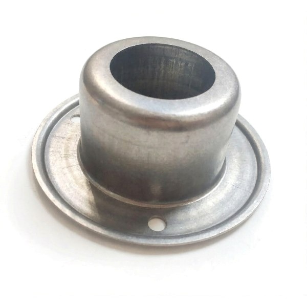
A reflector cone is an optical surface, so the draw must not ripple
A reflector cone is not a structural shell, it is an optical surface, and the difference changes everything about how it is drawn. A ripple of a few micrometres on a load-bearing wall is invisible and harmless; the same ripple on a reflector scatters light into a visible band and the part is scrap. We therefore treat the cone wall as a mirror-grade surface from the blank onward, because once a ripple is drawn in, no finishing step removes it without destroying the geometry.
The ripples come from two sources we control explicitly. The first is the blank holder: uneven hold-down lets the wall buckle into a shallow wave as it draws, so we set the force evenly and record it. The second is lubrication streaks: a non-uniform oil film draws unevenly and leaves a ripple that follows the streak, so we apply a metered, filtered lubricant and keep the die face clean. On a reflector the die surface finish is also specified, because the die is what the aluminium sees, and a polished die gives a smoother cone than a ground one.
We inspect the cone for ripple under grazing light on the first article, because a calliper cannot see a wave that a lamp can, and we reject on the optical check, not the dimensional one, because the optical check is the one the end customer will apply.
Cone angle is the spec, and the springback in aluminium moves it
The dimension that defines a reflector is the cone angle, because the angle is what directs the light, and the angle is exactly what aluminium springback moves. After the punch retracts, the cone opens by a fraction of a degree as the elastic strain releases, and that fraction changes where the beam lands. We compensate by drawing the cone to a slightly steeper angle than the drawing calls, then restriking to set the final angle, because a drawn angle alone carries the full spring variation and will not hold a beam tolerance.
The springback amount depends on the temper and the wall thickness, so we set the over-angle from the actual material, not a generic aluminium number, and we confirm it on the first article with an angle gauge or a CMM probe along the cone. A cone that is half a degree off throws its beam outside the intended pattern, and half a degree is easy to lose if the restrike is skipped.
The apex is the other angle-critical point. A blunt or ragged apex scatters the center of the beam, so we form the apex with a clean radius and check it, because the center of a reflector is where the eye looks first.
- Compensate the drawn cone angle for aluminium springback, then restrike to set it.
- Set the over-angle from the actual temper and thickness, not a generic value.
- Confirm the final angle on the first article with a gauge or CMM probe.
- Form and inspect a clean apex radius; a ragged apex scatters the beam center.
Specular reflectivity comes from the blank finish, not the anodise
Customers often assume the anodise makes the reflector shiny, but the anodise is a thin, mostly transparent layer; the specular reflectivity comes from the aluminium surface the draw leaves, and from the blank finish before the draw. A mill-finish blank draws into a matte cone; a bright-rolled or buffered blank draws into a brighter one, and the anodise only protects and slightly tints what is already there. We therefore specify the blank surface condition as a reflector characteristic, not just the alloy.
We also avoid drawing defects that the anodise magnifies. A draw mark or a die pick-up that is barely visible on bare aluminium becomes a bright scar under clear anodise, because the coating is uniform and the underlying flaw shows through. So the cone is drawn on a polished die with metered lubrication, as above, specifically so the anodise has a clean surface to sit on.
For maximum reflectivity we can buff the cone after drawing, but buffing removes the drawn surface and risks changing the angle, so we prefer to start from a bright blank and draw clean, keeping the angle control separate from the finish control.
There is also a choice between clear and coloured anodise that affects perceived brightness. A clear anodise keeps the aluminium’s natural tone and the highest specular return; a coloured anodise tints the reflection and is chosen for appearance or to cut glare, not to improve output. We specify the anodise type against the intended use, because a tint that looks right on the bench can shift the beam colour in a way the optical check will catch, and the anodise is the last step that can change what the lamp sees in the mirror.
The small-end bore seats the lamp, and its position runs off the apex
The small end of the cone usually seats the lamp or the lamp holder, and that bore has to be concentric to the cone axis and square to it, because the lamp aims along the axis. The bore position runs off the apex: any error in the cone symmetry or the draw centering puts the small-end bore off the optical axis, and the lamp then sits off-center and throws an asymmetric beam. We locate the small-end bore from the cone axis, not from the blank edge, and we machine it where the lamp fit is tight, referencing the cut to the cone.
The bore is also a size feature. A lamp holder that presses into the small end needs the bore held to a press-fit band, and we hold it machined at +/-0.03 mm rather than as drawn, because the lamp is the functional load. A bore that is round but off-axis is still a reject, so we check both roundness and concentricity to the cone, because the lamp cares about both.
Where the small end is open rather than bored, we still hold its circularity, because an oval small end seats an oval lamp and the beam skews accordingly.
A shade is thin, so the cone wall must hold a circle without a flange
A reflector shade is thin, often 0.5 to 1.0 mm, and it has no flange to stiffen the open end, so the cone wall itself has to hold its circle. A thin cone that ovals at the mouth throws light off to one side and sits crooked in its bezel, and there is no rim to trim it true as there is on a cup. We hold open-end circularity tight, typically within 0.1 to 0.15 mm total, and we win it at the trim, cutting the mouth concentric to the cone axis rather than to the blank.
The thin wall also means the cone dents easily in handling, so we specify a minimum practical wall and handle the first articles carefully, and we check circularity before anodise, because the coating will not hide an oval mouth. For shades that clip into a bezel, the mouth circularity is what lets the clip engage evenly, so it is verified as a primary characteristic, not a cosmetic one.
The wall thickness is also checked around the cone, because a thin spot in the wall is a thin optical surface that distorts locally, and a section on the first article confirms the wall is even around the circumference, not just at one point.
How we verify a cone that is judged by light, not by a calliper
A reflector cone is accepted by optical inspection more than by dimension, so the verification is built around the light, with dimensions supporting it. The first article carries the checks below and production is audited against it.
- Ripple is judged under grazing light on the cone wall; a calliper cannot see the wave a lamp will.
- Cone angle is measured with an angle gauge or CMM probe and confirmed against the springback-compensated value.
- Small-end bore is checked for size, roundness and concentricity to the cone axis where a lamp seats.
- Open-end circularity is measured with a three-point gauge referenced to the cone axis.
- Blank surface condition and any draw marks are recorded, because the anodise will show them.
- Material and heat are traced to the mill certificate so the reflector grade is documented.
Send the drawing or a sample shade, and the review returns the blank finish, the springback-compensated angle, and the small-end bore we will hold, so the cone that ships throws its beam true.
Drawing, machining and welding each win on different geometries; the guide to deep drawn covers works through those boundaries, and the full Precision Deep Drawn Parts range is reachable from the overview page.
Specifications
| Item | Aluminum Deep Drawn Reflector Cone Shade |
|---|---|
| Brand | AUNOV |
| Designing | Share your print, or send a part to be measured, a manufacturability review comes back with the quotation. |
| Tooling | Tooling designed and cut in house, stored under your part number. |
| Samples | Pre-production samples ship with dimensional data and material certs. |
| Materials | Aluminium leads the stock list for this part, alongside carbon steel (SPCC / DC01), 304 / 316 stainless steel, brass and copper, with grade selection confirmed at drawing review. |
| Surface finish | Plating, e-coat, powder coating, anodising or passivation as the drawing calls out, per the drawing. |
| Processing | Progressive deep draw stages with in-line annealing as the draw ratio demands, then pierced and CNC-machined in house. |
| Equipment | Mechanical presses 5-250 T, hydraulic presses 250-500 T, in-house CNC cells and a temperature-controlled inspection room. |
| Tolerance | As-drawn tolerance +/-0.1 mm, +/-0.03 mm on machined surfaces. |
| Delivery terms | FOB standard, DDP offered for EU and US, payment T/T or L/C, D/P for repeat accounts, call-off schedules supported. |
Frequently Asked Questions
Why is a reflector cone judged by light rather than by a calliper?
It is an optical surface, not a structural one. A ripple of a few micrometres on a load-bearing wall is invisible and harmless, while the same ripple on a reflector scatters light into a visible band and the part is scrap, so projection against a target tells the truth that dimensional measurement cannot.
What actually causes the ripples?
Two sources we control explicitly. Uneven blank holder force lets the wall buckle into a shallow wave as it draws, so we set the force evenly and record it; and a non-uniform oil film draws unevenly, leaving a ripple that follows the lubrication streak, so the lubricant is metered and filtered and the die face is kept clean.
Does the specular finish come from the blank or from the anodise?
From the blank, and this is the most common misconception about reflectors. Once a ripple is drawn in, no finishing step removes it without destroying the geometry, and the die surface finish is specified too, because a polished die gives a smoother cone than a ground one.
Why does the small-end bore run off the cone apex?
The small end seats the lamp, so the apex is what positions it, and a thin cone has no flange to reference from. Because the shade is thin, that small end also has to hold its circle without the stiffness a heavier gauge or a returned flange would give it, so the draw has to produce the geometry rather than rely on a finishing step to recover it.
Related Products


Request a Quote for This Part
Send a drawing or sketch — get material advice, tooling cost and a per-piece price within 24 hours (working days).