
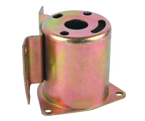
A stator housing has to be a magnet, a structure, and a heat path
A deep drawn steel stator housing with a flange is a single part with three demanding jobs, and they are more difficult to satisfy together than separately. It is a structural casing that has to hold the stator laminations and the whole rotating assembly against the forces an electric motor generates. It is a magnetic component – a drawn steel shell around the stack is part of the magnetic circuit, and its properties affect torque. And it is a heat path, because a motor’s losses have to get out through the housing. Change the wall for any one of those reasons and you have changed the other two.
We deep draw on maintained presses with blank size and lubrication logged per run, batch records filed so a repeat order starts from approved data, on 5-250 T mechanical presses plus 250-500 T hydraulics with in-line annealing, CNC turning centres for secondary operations, and CMM inspection. Drawn diameters to +/-0.05 mm with tighter bands confirmed against the drawing, and capability checked on the first article before the run continues. Stock runs to carbon steel in SPCC and DC01 grades, 304 and 316 stainless steel, aluminium and brass, with material substitutes proposed only with your written approval. This page is about the three jobs and where they conflict.
The magnetic job: the housing is part of the circuit
This is the aspect most often missed by people who only think of the housing as a can. A drawn steel shell surrounding the stator stack sits right next to the magnetic field, and it does three things:
- It shields. The housing is often the part that contains the field and keeps it from radiating outward, and that function depends on the material being a good magnetic shield.
- It carries flux. In many motor designs the housing is part of the return path for flux, and the flux density it can carry limits the motor’s output.
- It dissipates eddy currents. A drawn steel shell in a varying magnetic field can develop eddy currents, which waste energy and heat the housing. This is a genuine design tension, and it is one of the reasons the material grade is not free.
So the material choice is not only about corrosion or cost. Low-carbon steel such as DC01 is often the right choice precisely because its low carbon content gives good magnetic properties and a low loss factor. A higher-strength or higher-carbon grade would be stronger but magnetically worse. Where the housing is purely a shield and not part of the flux path, a different grade can be acceptable – and that determination belongs to the motor designer, which means it should be stated on the drawing rather than inferred.
The heat path: the housing is the motor’s radiator
Almost all of a motor’s losses end up as heat in the housing, and the housing’s job is to pass that heat to the outside air – sometimes directly, often through a mounting flange or a machine frame. Three design levers:
- Wall thickness and contact area. Heat flows through the housing wall and out through its outer surface. A thicker wall conducts better but pulls more material away from where the heat is generated, and it adds mass. For a steel housing the trade is usually worth making; for an aluminium one it reverses, because aluminium conducts about four times better and a thin aluminium wall out-performs a thick steel one.
- The flange. A flange bolted to a machine frame is a far better heat path than air, and it is often the reason a flange exists at all. Where the flange is the primary heat exit, its flatness and its bolt pattern – not just its size – determine the thermal performance, because a flange that does not sit flat conducts badly.
- Surface treatment. A bare or dark surface radiates heat better than a polished one. A painted or plated housing can be a slightly worse radiator, which is a minor but real effect and is rarely considered.
The structural job, and the forces it resists
The housing has to survive what the motor does, and the forces are not static:
- Radial forces. The rotating assembly is suspended and can move under imbalance, and the housing must hold it in place without ovaling enough to let the rotor rub.
- Axial thrust. Many motors have an axial component to their magnetic force, and this is reacted through the bearings and into the housing.
- Torque reaction. On a motor that drives something, the reaction torque has to go into the mount – which on a flanged housing means the flange’s bolts and the housing’s flange face.
- Thermal growth. The housing surrounds a part that gets hot. It will expand, and it has to be able to without the fit to the stack closing on the rotor. A housing whose diameter tolerance is too tight relative to the stack’s thermal growth will bind in service, and it will bind differently hot and cold.
A thicker wall buys conduction and shielding at the cost of a tighter band
This is the core of the design, and it is worth being explicit about the conflicts because they are where drawings need help:
| Thicker wall | Better heat conduction and better structure and better shielding – at the cost of mass, of material, and of a less tight fit to the stack. Usually the right direction for a steel housing, and the wrong one where mass or stator fit governs. |
|---|---|
| Higher-strength steel | Better structure, but poorer magnetic properties and higher eddy-current loss. Almost never the right answer for a housing that is in the magnetic field. |
| Aluminium housing | Excellent heat conduction and low mass, but a non-magnetic shield that is not part of the flux path, and a bigger thermal expansion mismatch against a steel stack. A design choice with real consequences, not a substitution. |
| Stainless Steel housing | Poor magnetic performance and much worse heat conduction than steel. Justified where corrosion resistance dominates and the housing is a shield rather than a circuit component. |
| A tighter drawn diameter | Better magnetic coupling and a tighter stack fit – but it removes thermal expansion clearance and can bind hot, and it raises the forming difficulty. This tolerance should be established with the motor designer, not from a general drawing band. |
The honest conclusion is that a stator housing’s material, wall and diameter tolerances should be decided together with the motor’s electrical and thermal design, and that a housing specified purely from a mechanical drawing will tend to be specified wrongly in one of the three directions.
Flange: the mounting and thermal interface
The flange is the part’s connection to everything else, and it carries three requirements:
- Bolt pattern matching the motor’s frame size. IEC and NEMA frame dimensions define the bolt spacing and the shaft centreline height, and the flange has to match – but the bolt holes’ relationship to the housing’s OD is set by the design and is a tolerance question.
- Flatness. The flange is the mount and the primary heat path. A flange that does not sit flat conducts less and can distort the housing under bolt preload. Flatness should be stated against a named surface and measured appropriately.
- Position. The flange’s bolt pattern has to be concentric with the housing’s bore, and the bolt holes have to be located properly rather than dimensioned as a chain. This is a true position requirement.
Drawing, production and traceability
Your drawing sets the part, unusual walls, threads or tolerances are feasibility-checked first, and the approved drawing is kept as the controlled master. Tooling is built and held under your part number so no tooling step is outsourced and the die remains dedicated to your part. Pre-production samples come with a full inspection report, the approved first article becomes the gauge reference, and production starts only after your written sign-off.
The production controls on this part are worth noting because they address the repeatability problem directly: blank size and lubrication are logged per run, and batch records are filed so a repeat order starts from approved data. On a motor housing that runs in volumes across years, those records are what make a repeat batch consistent – because the two variables that most affect a draw’s outcome, the blank’s size and the lubrication, are both process inputs rather than drawing features.
Six things that make a stator housing right
- The material, stated with the reason – and where it is a magnetic or part-circuit component, confirmed as low-carbon by the motor designer rather than substituted.
- Whether the housing is a magnetic shield, a flux path, or neither, because that determines which material properties matter.
- The drawn diameter tolerance, established with the stator fit and the thermal growth in mind rather than from a general band.
- The flange’s flatness and bolt pattern position, stated against a datum – because the flange is both the mount and the heat path.
- Which surfaces must not be coated, and whether dimensions are before or after finish.
- Any material substitution proposed in writing, which on this part is a genuine engineering decision rather than a purchasing convenience.
Finish is natural, plated or coated per the print, with the agreed finish logged and alternatives quoted with the quotation, samples approved in writing. One caution specific to this part: a coating on the housing’s outer surface can reduce its heat rejection slightly, and a coating on the flange face or the bore that must locate against a stack is a functional problem. Those areas should be masked, and saying so on the drawing is cheaper than finding it in the assembly.
If you are weighing drawing against machining or welding for this geometry, the guide to deep drawn covers sets out where each route wins; the full Precision Deep Drawn Parts range is linked from the overview page.
Specifications
| Item | Custom Deep Drawn Sheet Metal Deep Drawing Stator Motor Housing |
|---|---|
| Brand | AUNOV |
| Designing | Your drawing sets the part – unusual walls, threads or tolerances are feasibility-checked first; the approved drawing is kept as the controlled master. |
| Tooling | Tooling is built and held under your part number, so no tooling step is outsourced, and the die remains dedicated to your part. |
| Samples | Pre-production samples come with a full inspection report, so the approved first article becomes the gauge reference, and production starts only after your written sign-off. |
| Materials | Stock runs to carbon steel, 304 / 316 stainless steel, aluminium and brass; material substitutes are proposed only with your written approval. |
| Surface finish | Natural, plated or coated – the print decides, and the agreed finish is logged; alternatives quoted with the quotation, samples approved in writing. |
| Processing | Deep drawing on maintained presses, blank size and lubrication logged per run; batch records are filed so a repeat order starts from approved data. |
| Equipment | Mechanical presses 5-250 T plus 250-500 T hydraulics, with in-line annealing, with CNC turning centres for secondary operations and CMM inspection. |
| Tolerance | +/-0.05 mm on drawn diameters, tighter bands confirmed against the drawing; capability is checked on the first article before the run continues. |
| Delivery terms | FOB Ningbo or Shanghai, payment by T/T, L/C at sight or D/P; each volume tier carries its own quoted price. |
Frequently Asked Questions
What three jobs does a stator housing do at once?
It is a structural casing, part of the magnetic circuit, and the motor’s heat path. Changing the wall for any one of those reasons changes the other two, which is why the three jobs are harder to satisfy together than separately.
Why is wall thickness a conflict on a stator housing?
A thicker wall buys heat conduction and magnetic shielding but tightens the tolerance band and adds weight, so the wall is set from the most limiting of the three jobs rather than from one in isolation.
Which materials are used for a drawn stator housing?
Carbon steel in SPCC and DC01 grades for the magnetic path, plus 304 and 316 stainless steel, aluminium and brass, with substitutes proposed only with written approval. Drawn diameters are held to +/-0.05 mm.
How is a stator housing made traceable?
Batch records, a first-article capability check and CMM data are kept, and material certificates travel with the shipment. The typical minimum order is 1,000 pieces with a 24-hour quotation.
Related Products


Request a Quote for This Part
Send a drawing or sketch — get material advice, tooling cost and a per-piece price within 24 hours (working days).