
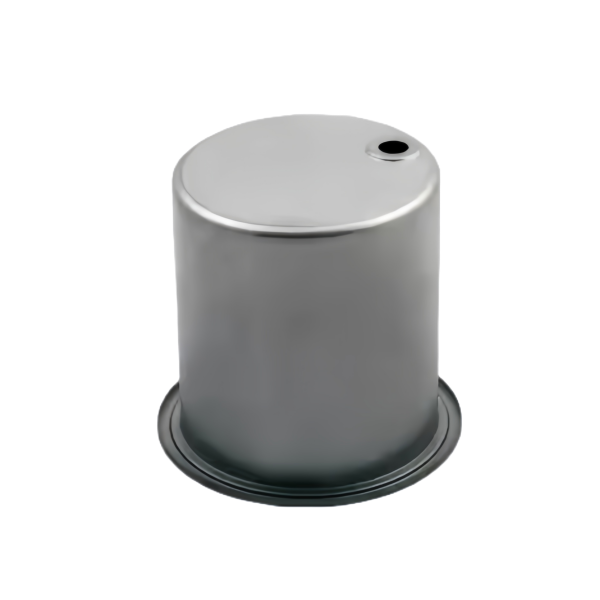
The steel deep drawn motor cup with a side drain hole is a motor housing variant where the customer needs liquid to leave the can without opening the end. The side hole looks trivial but it is the operation most likely to wreck the part, because piercing a hole in a curved, already-formed wall distorts the bore and the roundness if it is done carelessly. We pierce it as a precision secondary operation, referenced to the machined datum, not as an afterthought, and we support the wall from inside so the part cannot move when the punch lands.
Piercing the side drain hole without distorting the bore
A side hole is pierced through the cylindrical wall after the cup is drawn and the bore is machined, and the danger is that the punch pushes the wall inward and the cup goes out of round. We support the bore with a hardened mandrel inside the cup during the pierce, so the wall has nowhere to move and the bore stays true to +/-0.03 mm. The hole runs 4 to 8 mm depending on the drain rate, and the mandrel is sized to the finished bore so the pierce cannot dent the locating surface the motor depends on.
Hole position is set from the machined flange or bore datum, held to +/-0.15 mm, because the drain must clear the internal component and a hole 0.2 mm off can land on a winding or a lead. We pierce on a separate station from the trim so the hole is not compromised by trim springback in the same hit, because combining them is the usual cause of a hole that is on position only until the trim relaxes. The mandrel also gives the pierce a clean backup so the burr stays small and one-sided, which matters for the deburr step that follows.
- The mandrel is sized to the finished bore, so the pierce cannot dent the locating surface the motor depends on.
- Hole position is set from the machined flange or bore datum, held to +/-0.15 mm, because the drain must clear the internal component.
- We pierce on a separate station from the trim so the hole is not compromised by trim springback in the same hit.
- We confirm the hole clears the internal build envelope on the drawing before piercing, because a hole through a winding is a short.
Why the drain port sits after the machined seat
The motor cup usually has a machined seat or shoulder inside that locates a bearing or stator, and that seat must be generated before the drain hole is placed, because the hole position is referenced to it. If we pierced first and machined after, the seat cut would shift the wall and the hole would no longer line up with the internal clearances. So the sequence is draw, machine seat, then pierce drain, and we write that order into the process sheet so a setter cannot reorder it.
Where the drain must sit at a precise axial height relative to the seat, we gauge it from the machined face, not from the drawn top, because the drawn top carries the +/-0.1 mm draw tolerance and the machined face carries the tight one. The seat itself is turned concentric with the bore in one set-up, then the hole is pierced relative to that same set-up’s datum, so the drain and the seat share one reference chain and the tolerance stacks cleanly instead of doubling. This reference discipline is the difference between a drain that lines up every time and one that lines up on the first piece and drifts on the thousandth.
- We write the operation order into the process sheet so a setter cannot reorder it and move the hole off datum.
- Where the drain must sit at a precise axial height relative to the seat, we gauge it from the machined face, not from the drawn top.
- The seat itself is turned concentric with the bore in one set-up, then the hole is pierced relative to that same set-up’s datum.
- We flag any drawing that pierces the drain before the seat, because the position will not hold once the seat is cut.
Deburring a through-hole in a formed motor cup
A pierced side hole leaves a burr on the inside that, left alone, becomes a place for swarf to collect and a hazard to the winding or rotor. We break the internal burr with a dedicated deburr tool or a tumble pass, and we verify it because a missed internal burr is exactly the kind of defect that surfaces only after the motor is built and the customer finds a short or a noise. The internal burr is the defect most easily skipped on a small run, which is why we sample it per batch rather than only at first article.
For coated cups we deburr before plating so the plate does not bridge the burr and leave a sharp lip after, because a plated burr is harder than the base and cuts whatever it touches. Where the drain edges a grommet or tube, we roll or chamfer the hole so the seal seats without cutting itself, because a sharp hole edge slices a rubber grommet on insertion and the seal fails quietly. The deburr is not cosmetic on this part; it is what keeps the inside of the motor clean.
- Internal burr is checked with a probe or a coloured marker test at first article and sampled per batch.
- For coated cups we deburr before plating so the plate does not bridge the burr and leave a sharp lip after.
- Where the drain edges a grommet or tube, we roll or chamfer the hole so the seal seats without cutting itself.
- We specify the burr direction on the drawing, because a burr that points into the motor is worse than one that points out.
Holding the cup depth while the side wall is pierced
Piercing pushes axial force into the cup, and on a thin-walled motor cup that force can shorten the part or bow the open end if the cup is not clamped. We clamp the flange face hard against the die during the pierce and support the open end, so the depth holds to +/-0.1 mm and the mouth stays square to the bore. The open-end support is a light mandrel that stops bow without marking the bore, since the bore is already machined and a mark there is a reject.
Depth is re-checked after the pierce operation, not just before, because clamping drift is the silent failure – the cup measures right before the hole and short after, and nobody checks the second time. We log the pierce clamp pressure per part number so a re-order repeats the same support geometry, because a different clamp pressure shortens the cup a different amount and the stack height drifts. Holding depth through the pierce is the step that protects every dimension downstream of the flange.
- We clamp the flange face hard against the die during the pierce and support the open end, so the depth holds to +/-0.1 mm.
- The open-end support is a light mandrel that stops bow without marking the bore, since the bore is already machined.
- Depth is re-checked after the pierce operation, not just before, because clamping drift is the silent failure.
- We log the pierce clamp pressure per part number so a re-order repeats the same support geometry.
Carbon steel finish choice for a draining motor cup
A cup that drains also sees what it drains – often water, oil or condensation – so the finish has to survive a wet interior. We default to zinc plating for indoor motors and to e-coat or nickel where the interior stays damp, and we plate or coat after the drain hole is pierced so the hole edge is protected too, because a bare pierced edge is exactly where rust starts on a draining part.
We specify whether the interior or only the exterior is coated, because a fully coated interior can affect the stator fit and a partially coated one can look like a mistake. Nickel is chosen where the drain carries corrosive fluid, since zinc would sacrificially fail in that service and leave the cup unprotected within a season. The finish thickness on the hole edge is checked, because thin coating at a pierced edge is the first place rust starts and the place a thickness gauge usually misses if we are not looking for it.
- We default to zinc plating for indoor motors and to e-coat or nickel where the interior stays damp.
- We plate or coat after the drain hole is pierced so the hole edge is protected too, because a bare pierced edge is where rust starts.
- Nickel is chosen where the drain carries corrosive fluid, since zinc would sacrificially fail in that service.
- The finish thickness on the hole edge is checked, because thin coating at a pierced edge is the first place rust starts.
How we verify a motor cup with side drain hole
Verification centres on the thing that can go wrong here: the hole relative to the machined bore. The checks below are what we actually run, and a lot is released only when the sampled pieces pass all of them, because a distorted cup is the failure mode unique to this part.
- Bore and seat concentricity confirmed on the CMM against the machined datum.
- Drain-hole position and diameter measured from the datum, with the mandrel-supported pierce confirmed.
- Internal burr inspection at the hole, by probe or marker test, sampled per batch.
- Cup depth re-checked after the pierce operation for clamping drift.
- Finish thickness at the hole edge and adhesion by tape pull.
- Roundness of the cup after pierce, because distortion is the signature failure of this part.
The design decisions behind a part like this — draw ratio, wall thinning, radii and trim — are worked through with numbers in our deep drawn covers guide, and the Precision Deep Drawn Parts pages collect the rest of the family.
Specifications
| Item | Steel Deep Drawn Motor Cup with Side Drain Hole |
|---|---|
| Brand | AUNOV |
| Designing | A drawing file or a physical sample starts the review, a manufacturability review comes back with the quotation. |
| Tooling | Dies engineered and produced in our own toolroom, held under your part number. |
| Samples | The first-article set ships with a full dimensional report and mill certificate. |
| Materials | Carbon steel (SPCC / DC01) is the primary stock for this part, alongside 304 / 316 stainless steel, aluminium, brass and copper, and the grade is fixed at the drawing review. |
| Surface finish | Finish options: plating, e-coat, powder coating, anodising or passivation, as called out on your print. |
| Processing | Deep drawing in stages, in-line annealing where needed, with piercing and finish machining under the same roof. |
| Equipment | Press capacity from 5 to 500 T across mechanical and hydraulic lines, CNC turning centres and a climate-controlled CMM room. |
| Tolerance | Tolerances to +/-0.1 mm as drawn, machined features held to +/-0.03 mm. |
| Delivery terms | FOB is standard; DDP offered for EU and US, T/T or L/C, D/P on repeat business, call-off scheduling supported. |
Frequently Asked Questions
How is the side drain hole pierced without distorting the bore?
After the cup is drawn and the bore machined, a hardened mandrel supports the bore during the pierce so the wall has nowhere to move and the bore stays true to +/-0.03 mm. The mandrel is the control, not an afterthought.
Why is the drain port pierced after the machined seat?
Position is set from the machined flange or bore datum to +/-0.15 mm so the hole clears internal components, and piercing on a separate station avoids trim springback moving it after the fact.
What size is the side drain hole and how is burr controlled?
The hole runs from 4 to 8 mm depending on the drain rate, and the mandrel backs the pierce for a small, one-sided burr that is straightforward to deburr in the following step.
Which materials suit a draining motor cup?
Carbon steel, 304 and 316 stainless steel, aluminium and brass, with finish per the print and drawn diameters to +/-0.05 mm. The typical minimum order is 1,000 pieces with a 24-hour quotation.
Related Products


Request a Quote for This Part
Send a drawing or sketch — get material advice, tooling cost and a per-piece price within 24 hours (working days).