
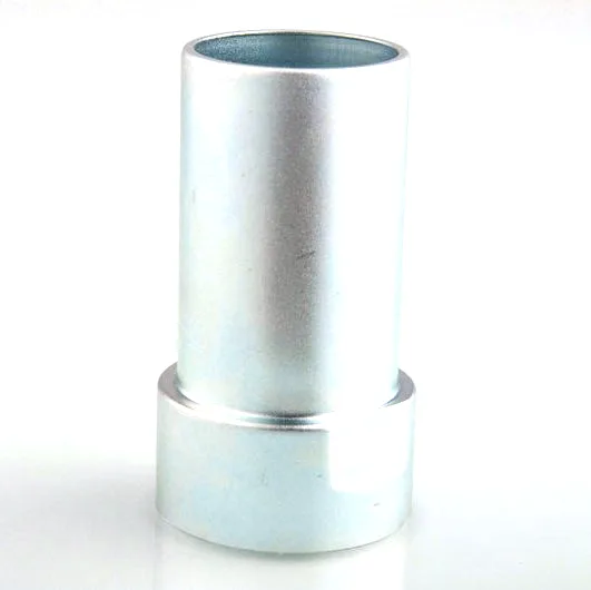
A cylindrical shell is a buckling part, not a strength part
A deep drawn cylindrical shell looks like a tube, and a tube is the classic strong shape: material where the load is, nothing wasted. That intuition is right for tension and wrong for almost every real service condition, because a thin cylindrical shell loaded from the outside fails not by breaking but by buckling – the wall dimples inward, the dent grows, and the part is scrap well before any material reaches its strength.
For a shell that is evacuated, pressurised from the inside, thermally cycled, or simply handled, this changes how the part should be drawn and what should be specified. We draw these as multi-stage deep draws with interstage annealing, trimmed and pierced in following dies, running mechanical presses from 5-250 T and hydraulics from 250-500 T with in-line annealing furnaces. Formed features are held to +/-0.05 mm with capability data on the critical dimensions. This page is about the wall, because in a shell the wall is the whole design.
Why external pressure inverts the design
Under internal pressure, a cylindrical wall works in hoop tension and the stronger and thicker it is the better it performs. Under external pressure the same wall works in hoop compression, and compression in a thin shell has almost no reserve – the failure mode is a geometric instability, not a strength limit. Two consequences follow directly, and both should shape the drawing:
- Length is a weakness, not a strength. For a given material and thickness, a longer shell buckles at a lower external pressure than a short one. Adding length to a shell that must resist vacuum is one of the most expensive changes you can make, and it costs material rather than saving it.
- Roundness is structural. A shell that is even slightly out of round is already partway to a buckle. Ovality from the draw, and any ovality introduced later by handling or by a fixture that clamps the shell, permanently reduces the buckling pressure. On a vacuum-rated shell, ovality is a specification dimension, not a cosmetic one.
Draw quality therefore matters more than on almost any other deep drawn part. The shell wall should be free of draw lines, tool marks, and any local thickening that breaks the symmetry of the section – and a batch that has been handled roughly enough to develop a flat spot is a batch that will not test to its rated vacuum.
Wall thickness distribution along the draw
Deep drawing thins the wall, and it thins it unevenly. The thinning is predictable, which is useful, because the drawing engineer can compensate for it rather than fight it. The pattern for a plain cylindrical cup drawn from a blank:
- At the cup wall, roughly 80-90% of blank thickness. The wall is stretched as the blank is pulled over the punch radius.
- At the punch nose radius, the maximum thinning. The material changes direction most sharply here, so this is the thinnest point in the whole part and the location of any split or tear.
- At the cup bottom, close to blank thickness. Material here is supported by the die and flows rather than stretches, so the bottom is the strongest section.
- At the rim of the flange, close to blank thickness. The flange is barely worked.
Two practical uses. If a shell needs a specific wall in a specific region – say, a thinner wall in a section that has to flex – the blank is offset and the geometry adjusted so the drawn result lands on nominal there. And if a shell must resist a pressure, the punch nose radius is increased, because a tight nose radius is the thinnest point in the part and it is exactly where a burst or a buckle will start.
The wall tolerance on a drawn shell is inherently one-sided in practice. A thick wall will rarely cause a rejection; a thin wall can. That is why a specification that says only “plus or minus” leaves the drawing open to an argument about which end of the band actually matters, and it is worth naming the thin-side limit explicitly.
Interstage annealing and why it is on the route
Every stage of a deep draw consumes ductility. The first stage uses the material’s as-rolled temper; the second stage works on a material that has already been stretched, and if the accumulated strain exceeds what the grade can take, the wall either thins unevenly or splits at the punch nose. Annealing between stages resets the material and makes a further reduction possible.
There is a cost to annealing that has to be managed rather than ignored. The part comes out of the furnace with an oxide skin, it changes dimension slightly as it heats and cools, and it needs a cleaning and a dimensional check afterwards. So annealing is not free – it is a scheduled operation with a control plan around it, which is exactly why we run in-line annealing furnaces rather than sending parts out to a subcontractor. In-house annealing also means the annealing temperature is recorded against the part number, so a later question about a fatigue complaint has an answer.
The other thing annealing does is interact with the surface finish. If a shell is to be plated, an oxide skin left by annealing will affect plating adhesion, and if a shell is in a clean or oxygen-sensitive service, the annealing atmosphere has to be controlled for brightness. Those requirements need to be stated at quotation rather than discovered at the plating shop.
Roundness, concentricity and the second operation
A shell that has to mate with something – a cover, a tube, an end plate, a drawn-in flange – needs the open end to be true. Two features control this, and on a deep drawn shell they are usually separate operations:
- A sizing or flanging station. Pressing the open end down to a controlled diameter and length sets the shell’s roundness and its length at the same time. This is a work-hardening operation that also raises the stiffness of the rim.
- A machined seat. Where a shell needs a face that a seal presses against, or a bore that registers, that face is machined on a CNC turning centre. This is where a tight band lives – tighter than a drawn feature – because a drawn face cannot hold a sealing surface.
We run CNC turning centres for these secondary operations and inspect in a climate-controlled inspection room, which matters more than it sounds: a thin shell changes dimension with temperature, so measuring a shell at 30 C and then using it at 5 C puts a real error into a dimension that was nominally perfect.
Materials and where the real trade sits
Carbon steel is the default for a shell that is structural or shielded. It draws well, it is forgiving in the die, and it is the cheapest route to a good roundness. Where the shell is exposed to moisture or a corrosive atmosphere, 304 or 316 stainless steel removes the coating variable; stainless steel draws at higher tonnage, work-hardens faster – which makes interstage annealing more important, not less – and its higher yield strength means more springback at any given geometry.
Aluminium is chosen where mass matters or where the shell is a heat-transfer surface. It draws at lower tonnage and springs back differently, and its surface means the annealing and cleaning steps need to be more carefully controlled than for steel – retained lubricant under an oxide skin is a corrosion site. Brass is chosen for conductivity and for corrosion behaviour in specific media, and it draws well in the sizes a shell usually needs.
Surface treatment is plating, coating or polishing to suit the drawing, with masking and laser marking available where needed. On a shell, masking is common – a face that has to stay a sealing surface or a bearing surface gets masked rather than plated, and that is a quotation line rather than a detail to be discovered afterwards.
What to review before the die is cut
Send drawings, or send a sample to be measured. DFM notes come back before any tooling is cut, and the agreed version governs every later batch. The checks that change a cylindrical shell drawing most often are these:
- Is the shell under external pressure, and if so how much and for how long? That single question converts the part from a strength problem into a buckling problem and determines both the wall and the length.
- Where is the open end, and is roundness a requirement or a preference? If it mates, roundness is a specified tolerance and it needs a sizing station and a way of measuring it – typically a roundness check in a fixture, not a micrometer across one diameter.
- Does the wall have to be uniform, and how thin is the thinnest it may become? This decides the punch nose radius, the number of stages and whether annealing goes between them.
- Is any face going to be machined, and what does the stamping have to leave behind? Machining allowance must be designed in, not hoped for.
- Is there a coating on the inside, the outside, or selectively? A galvanised or plated shell with a masked sealing face needs saying on the drawing.
Progressive and drawing dies are designed and built in house, so no tooling step is outsourced, and the charge is refundable against agreed volumes. First articles verify the whole flow before the run is released. Delivery is quoted per the quotation, and repeat orders reuse the approved first article – which for a shell is worth stating explicitly, because a shell that is in tolerance on the first article and drifts on the fiftieth is nearly always a wall-thickness or anneal-schedule question, and the approved first article is the only fixed reference you have.
Choosing between drawing, machining and welding comes down to the shape of the part: the guide to deep drawn covers sets out where each route wins, and the overview page links through to the full Precision Deep Drawn Parts range.
Specifications
| Item | Deep Drawn Cylindrical Shell |
|---|---|
| Brand | AUNOV |
| Designing | Send drawings, or send a sample to be measured – DFM notes are returned before any tooling is cut; the agreed version governs every later batch. |
| Tooling | Progressive and drawing dies are designed and built in house, so no tooling step is outsourced, and the charge is refundable against agreed volumes. |
| Samples | First-article samples ship with a dimensional report and material certificate, so the part is proven before it is made in volume, and production starts only after your written sign-off. |
| Materials | Materials held include carbon steel, 304 / 316 stainless steel, aluminium and brass; the final grade is fixed with the drawing review. |
| Surface finish | Plating, coating or polishing to suit the drawing; masking and laser marking available where needed. |
| Processing | Multi-stage deep drawing with interstage annealing, trimmed and pierced in following dies; first articles verify the whole flow before the run is released. |
| Equipment | Mechanical presses from 5 to 250 T and hydraulic presses 250-500 T, with in-line annealing furnaces, backed by CNC turning centres and a climate-controlled inspection room. |
| Tolerance | +/-0.05 mm on formed features, with capability data on critical dimensions; GD&T per drawing, PPAP-style reports on request. |
| Delivery terms | FOB, with DDP offered for EU and US addresses, T/T or L/C, with D/P accepted on repeat business; each volume tier carries its own quoted price. |
Frequently Asked Questions
Why is a cylindrical shell a buckling part, not a strength part?
Under external pressure the thin wall dims inward and grows into a dent well before the material reaches its strength, so the design is governed by buckling rather than by breaking load. That changes what should be specified.
How does wall thickness distribute along the draw?
The wall thins where the draw is deepest and the metal flows fastest, so the thickness distribution is planned at the tooling stage and checked at the critical sections. Interstage annealing keeps the wall thinning even.
What materials are used for cylindrical shells?
Carbon steel, 304 and 316 stainless steel, aluminium and brass, with the real trade sitting between cost, corrosion duty and how the wall behaves under load. Formed features are held to +/-0.05 mm.
How is a cylindrical shell quoted and inspected?
Multi-stage deep draws with interstage annealing, trimmed and pierced in following dies, with roundness and concentricity checked on the CMM. The typical minimum order is 1,000 pieces with a 24-hour quotation.
Related Products


Request a Quote for This Part
Send a drawing or sketch — get material advice, tooling cost and a per-piece price within 24 hours (working days).