
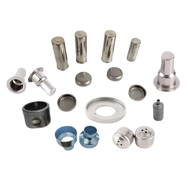
The Assorted Deep Drawn Cups Caps and Sensor Shells family spans the three workhorse shapes of our floor: cups with closed bottoms, shallow caps that finish in one hit, and sensor shells whose geometry is dictated by electronics rather than mechanics. The pages of this catalogue tell the engineering story per shape, because a family order is really three different processes sharing a press line – and the buyer who understands the differences gets honest tooling quotes and honest lead times.
Three shapes, three cost structures on one press floor
A cap is the cheapest thing we make well: shallow, single-stage, fast cycling, with the engineering effort concentrated in edge quality rather than forming risk. A cup costs more per part because depth buys difficulty – every diameter of depth past the first stage ratio adds a draw stage, a die set and an anneal decision. A sensor shell is priced by neither rule, because its features are driven by what must fit inside: a board, a potting compound, a connector. When an assorted order contains all three, we quote per line item rather than per kilogram, and the quotation shows why.
- Caps below roughly half a diameter in depth usually run one-stage with in-die piercing where holes are needed, which is the shortest tooling lead time and the fastest cycle in the plant.
- Cups past about twice diameter in depth run staged drawing on the hydraulic presses with in-line annealing between passes; the stage table is itemised in the quote because it is the tooling budget.
- Sensor shells are quoted against the cavity they must hold: the housing’s depth, bore and mouth features are dimensioned by the customer’s electronics, and the drawing review asks for them early so the tooling is not re-cut after the first potting trial.
Trim and edge conditioning: the detail that separates good caps from cheap ones
On a shallow cap, the forming is easy and the edge is everything. A trimmed rim carries a burr on one face or the other depending on trim direction; the burr is fine where the cap sits inside a housing and unacceptable where a person, a gasket or a wire loom touches the edge. Edge conditioning is therefore specified per drawing, not per factory habit – and the specification has three honest levels with three different costs.
- As-trimmed: economical, correct for internal-only edges; the burr direction is controlled by the trim tooling so it never faces a gasket or a glove.
- Deburred: the standard for exposed edges; burr height is held under a written limit and checked under magnification at first article and per lot.
- Curled, rolled or beaded: where the rim is structural – a sealing bead, a snap flange, a stiffening curl – the rim is formed in the die or a restrike, which adds a station but removes an entire finishing operation from the part’s story.
The curl deserves mention because it is a cost inversion: adding a formed rim to a cap is one more die station at tooling time, and it eliminates a deburring pass, a gasket retainer or a bracket from the customer’s assembly. The drawing review raises it when the part’s duty suggests it.
Seamless conductivity: why sensor shells are drawn, not assembled
When a deep drawn shell houses a sensor – temperature, pressure, magnetic, proximity – the wall is doing electromagnetic work. A one-piece drawn wall provides an uninterrupted conductive path for shielding and a uniform thermal path from the medium to the element; a welded or seamed enclosure interrupts both at the seam. Drawn sensor shells also carry the seamlessness into mechanical duty: no weld bead inside the cavity, no crevice to trap potting compound or cleaning fluid.
- For housings that must shield, the drawn wall’s continuity is the shielding; any later apertures – connector ports, vent holes – are pierced and their edge condition controlled, because an aperture with a ragged edge is an antenna at high frequency.
- For housings that must conduct heat, wall uniformity is the thermal specification: we map thickness at named sections on the first article so the thermal path is documented, not assumed from the nominal gauge.
- Material follows the duty: SPCC / DC01 for dry indoor electronics, 304 / 316 where the medium is wet, brass or copper where conductivity is the primary function – and the stock list carries all of them with mill certificates per heat.
Depth-to-diameter: the number that prices every part in this family
Across cups, caps and shells, one ratio predicts the tooling bill better than any other single number: depth divided by diameter. Below about 0.5, the part is a cap-class draw – single stage, fast, cheap. Between 0.5 and 2, the part is a cup that wants two or three stages. Past 2, the part is a deep shell whose stage count, anneal points and tooling lead time all scale with the ratio. This is why we ask for the drawing before discussing price: two parts that look identical in a photo can sit on opposite sides of a stage boundary.
- The stage ratio itself is a design lever: opening a bottom radius by half a millimetre or relaxing a corner can drop a stage from the plan, and the drawing review quotes the trade so the designer can spend tolerance where it buys money.
- Anneal points are honest costs: every added anneal is furnace time and handling, and we show them as line items rather than burying them in overhead.
- Where an assortment mixes depth classes, the quote shows the stage tables per line item – the buyer sees exactly which part in the family carries the tooling weight.
Piercing, hole patterns and what they do to the tooling plan
Most parts in this family carry holes: vent slots in sensor shells, mounting patterns in caps, drain or wire passages in cups. Hole patterns are where progressive tooling earns its keep – a multi-station progressive die pierces and forms in one press cycle per part – but the pattern’s geometry decides whether progressive is even available. Hole-to-wall distance, hole size relative to gauge, and hole position relative to the trim line each have a minimum, and a pattern that violates them moves the part from piercing-in-die to piercing-in-a-secondary-operation with a cost and a tolerance consequence.
- Hole position tolerance on a pierced pattern is held relative to the die’s stations – typically to the ±0.1 mm class of the drawn part – and machined afterwards to ±0.03 mm where a pattern must register precisely, with the review saying which pattern elements genuinely need it.
- Slotted and shaped apertures for vents or connectors are pierced with the form taken into account: a hole that is round in the flat blank is not round after the wall draws, so apertures on drawn walls are pierced in the die at the station where the wall is final.
- Burr direction on pierced apertures is planned like a cap’s trim edge – burrs point away from gaskets, connectors and gloved hands.
How we verify an assorted family order
Assorted does not mean averaged: each line item in the family runs its own acceptance sequence, per its own part number.
- First article per line item on the CMM in the climate-controlled room: envelope dimensions, wall thickness at the documented thin sections, and the named characteristics each drawing calls – depth on cups, edge condition on caps, cavity and aperture data on sensor shells.
- Edge and aperture condition: burr height against the written limit, under magnification, on trim edges and pierced apertures alike.
- Wall mapping where the drawing’s function depends on it – sensor cavities, sealing beads and mounting flanges all get named-section thickness data on the report.
- Finish verification where plating, e-coat or powder is specified: thickness and adhesion on the first article, with the finish locked to the drawing revision.
- Traceability per part number: mill certificates per heat, stage tables, press settings archived, and each line item’s signed first article governing its production batches under ISO 9001 – so reorders of any single family member start from data that already worked.
Drawing, machining and welding each win on different geometries; the guide to deep drawn covers works through those boundaries, and the full Precision Deep Drawn Parts range is reachable from the overview page.
Specifications
| Item | Assorted Deep Drawn Cups Caps and Sensor Shells |
|---|---|
| Brand | AUNOV |
| Designing | Send drawings, or send a sample to be measured, our engineers reply with a manufacturability assessment and pricing. |
| Tooling | Every die designed and built in our toolroom, each die held against your part number. |
| Samples | First-off samples are sent with a full dimensional report and material certification. |
| Materials | Material options span carbon steel (SPCC / DC01), 304 / 316 stainless steel, aluminium, brass and copper, and the grade is fixed at the drawing review. |
| Surface finish | Finish options: plating, e-coat, powder coating, anodising or passivation, per your print. |
| Processing | Staged deep drawing, with in-line annealing where the draw ratio requires, pierced and finish-machined on the same floor. |
| Equipment | Our press floor runs 5-250 T mechanical and 250-500 T hydraulic presses, CNC cells plus a temperature-controlled CMM room. |
| Tolerance | +/-0.1 mm as-drawn, machined features held to +/-0.03 mm. |
| Delivery terms | Standard terms FOB, DDP offered to EU and US, payment T/T or L/C, D/P for repeat accounts, call-off schedules and blanket orders supported. |
Frequently Asked Questions
Why do three similar shapes in one carton have three different cost structures?
Because depth buys difficulty. A shallow cap is single-stage and fast-cycling, with its engineering effort spent on edge quality rather than forming risk; a cup costs more per part because every additional diameter of depth past the first stage ratio adds a draw stage and a die station. Depth-to-diameter is the number that prices everything in this family.
What separates a good cap from a cheap one if forming risk is low?
Trim and edge conditioning. There is very little to get wrong in the draw itself on a shallow cap, so what distinguishes a part that assembles cleanly from one that snags, cuts fingers or leaves debris is how the cut edge is conditioned and deburred.
Why are sensor shells drawn rather than assembled from pieces?
Conductivity. Every joint in a conductive path is a place the signal has to cross an interface, and a drawn shell gives continuous material with no seam to vary. Where consistent electrical behaviour is the requirement, the seamless shell is the reason for specifying it rather than a quality upgrade.
How do pierced hole patterns affect the tooling plan on an assorted order?
Hole patterns are usually what stops drawing reuses across members that otherwise look interchangeable. Each pattern needs its own piercing station, so two caps that are identical until someone specifies different holes are effectively two tooling items, and it is cheaper to say so at enquiry than to price separately later.
Related Products



Request a Quote for This Part
Send a drawing or sketch — get material advice, tooling cost and a per-piece price within 24 hours (working days).