
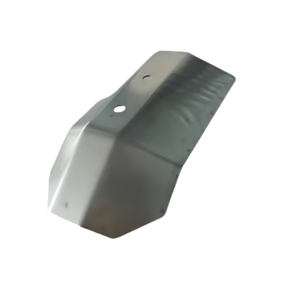
An angled steel cover solves a specific packaging problem: the assembly it shields is not square to the mounting surface. A bend line — typically 15° to 90° — lets one drawn piece cover a horizontal face and turn down over a vertical one, with the cable entry on the low side and the mounting holes where your bracket needs them. This page shows how that angle is formed, why the hole pattern is pierced after drawing, and what keeps piece one hundred identical to the first.
What an angled cover is, geometrically
Take a shallow drawn shell and add one formed bend across it: the result is an angled cover — a face plate, an inclined wall and often a short return flange, all from one blank with no welds. Compared with bending up a flat blank, the drawn version keeps continuous material through the bend, so there is no corner gap to seal and no weld to corrode. Compared with machining the angle from solid, it is lighter, cheaper at volume, and the wall thickness stays uniform instead of being cut away.
Angles in this range are formed two ways, and the choice matters for your tolerances:
- Drawn with the angle in the die — for steeper, repeatable angles on production volumes. The die holds the angle, so springback is compensated inside the tool, not on your assembly jig.
- Drawn flat, then restrikes — the shell is drawn square and the angle is formed in a second operation through a restrike die. This suits parts where the hole pattern must stay true to the flat face, because the holes are pierced after the final geometry exists.
The angle problem: springback and how it is beaten
Every formed angle springs back when the punch releases — steel recovers a fraction of a degree to a few degrees depending on thickness, grade and the radius around the bend. Left uncompensated, that is why an angled cover sits proud on one side of its gasket. Three things keep the angle honest:
- Restrike with overbend. The part is formed a little past the target angle so springback lands on it, not short of it. The overbend value is die-specific and recorded in the tool file.
- Coining the bend line where the print allows it — a shallow coin at the radius sets the angle and stiffens the bend against handling.
- Angle gauged between operations, not just at the end. The hundredth piece has to match the first; that is why the angle is checked after forming and again after piercing, so a drifting die is caught mid-run, not on your line.
Mounting holes: pierced after, never before
The hole pattern on this cover is functional — it bolts to your assembly — so its position discipline is the core of the process:
- Form first, pierce second. Piercing before drawing distorts hole positions as the metal flows; holes placed after the final geometry, through position fixtures, land where the print says without rework.
- Burr-free on the second operation. Freshly ground tooling and correct clearance give clean hole walls; edges are deburred so the part arrives assembly-ready.
- Pattern verified to the print, not to the die. First-article inspection measures the hole pattern dimension by dimension on the CMM against your drawing — the die being “right” is not the standard; the print is.
Material and finish
Standard stock is carbon steel (SPCC / DC01 or to print); equivalents are feasibility-checked against your drawing before quoting. Where the cover sees moisture, zinc plating or powder coat after forming is the usual route — plating after piercing keeps hole walls protected too. Stainless Steel versions trade a higher material and forming cost for no finish at all, which in washdown environments often ends cheaper overall. The finish is set by the drawing: natural, plated or coated, with masking where contact faces must stay bare.
Tolerances we hold
| Feature | Control | Note |
|---|---|---|
| Bend angle | Per print, springback-compensated | Angle gauged between operations; overbend recorded in the die file |
| Hole pattern | Per print, CMM-verified at first article | Pierced after forming through position fixtures |
| General form | ±0.05 – ±0.10 mm | Finer bands confirmed from capability data before quoting |
| Wall thickness | Held to print | Thinning at the bend radius monitored; die radii sized to the sheet |
| Edges | Burr-free | Deburred on arrival, ready for your line |
Where angled covers are used
Typical duty for this geometry: shielding exposed actuator or sensor faces while cable entry passes through the low side, covers on HVAC and appliance assemblies where the mounting plane is not the working plane, and lighting reflectors that need an inclined face from one piece. Related geometries worth a look: deep drawn cover (flat and domed versions), vented cover with louver slots for airflow duty, and the parent range on precision deep drawn parts.
Production discipline behind the part
Dies for angled covers are maintained by stroke count rather than by waiting for drift, which is what keeps the angle and hole pattern stable across a long run. Dimensional reports and material certificates are issued with the first article; production batches follow the sampling plan agreed at approval, under the ISO 9001 system described on the quality control page. Small orders are welcome — prove the part, then scale. Samples of the angled cover are supplied with a manufacturability review before tooling, through the quote request page.
Questions we get about angled covers
Can the angle and the hole pattern both hold tolerance?
Yes — but the order of operations is what makes it true: draw (or restrike) the angle first, then pierce the holes against the final geometry. Parts that need holes and angle in one stroke give up accuracy on both.
What angles are practical to form?
Commonly 15° to 90° in steel sheet from 0.15 to 3.0 mm. Steeper angles and tighter inside radii raise forming load and thinning; the feasibility review at quotation will flag any angle that wants a machined feature instead.
Can you match an existing angled cover without a drawing?
Send the sample. It is measured into a controlled drawing, the angle is gauged, and a first article with a dimensional report is approved before production — so the replacement is a repeat of a defined process, not a guess from a physical part.
Angled geometry changes every number on the print — springback allowance, trim line, flange flatness. The deep drawn covers guide covers the base cases that angled parts build on.
Request a Quote for This Part
Send a drawing or sketch — get material advice, tooling cost and a per-piece price within 24 hours (working days).