
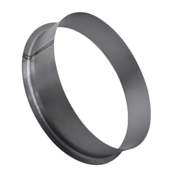
The Steel Deep Drawn Ring Band Flanged Sleeve is a sleeve that ends in a flange, and the flange changes everything about how the part is judged: it is at once the mounting datum, the stiffness backbone and the seal face of the assembly. This page covers how a flanged ring-band is drawn in one shell, where its tolerances concentrate, and the checks that make the flange a reliable interface instead of a decorative rim.
The flange as datum: what the mounting face must actually deliver
On most sleeve prints the flange is dimensioned as a diameter and a thickness. In the assembly it is three things at once: the surface that seats against the housing, the plane from which height is measured, and – frequently – the face carrying a gasket or an O-ring land. Each of those jobs is a different geometric requirement. Seating demands flatness. Height demands squareness of the flange to the sleeve axis. Sealing demands surface texture on the land. A drawing that captures all three produces a part that assembles the way the CAD model imagines; a drawing that captures only the diameter produces a part that seats crooked and leaks.
- Flange flatness is the named check for the seating job – measured at first article on the CMM and gauged per lot – because a flange that rocks on its housing transmits clamping torque unevenly and relaxes the bolt pattern over time.
- Squareness of the flange to the bore is the height job: it is the difference between a sleeve standing true in its pocket and one that stands tilted with the bore’s axis canted relative to the housing.
- The seal land’s texture is the gasket job: where the flange face carries a seal, the as-drawn texture is usually not good enough and the land is machined to a stated Ra in the same setup as the bore.
Ring-band forming: getting flange and band from one blank
The part’s cross-section reads like a stepped cup turned inside out – a band of cylindrical wall closing into a flange rim – and the drawing route for that shape is a staged flow: the early stages form a shallow cup that becomes the band, and the flange develops from the cup’s mouth as later stages flatten and widen the rim against a flanging die. The metal that ends in the flange has barely moved from the blank’s original plane; the metal in the band has been drawn down and thinned; and the transition between them is where the process either succeeds or wrinkles.
- The corner between band and flange is the thin-section of this geometry: metal flows around it in two directions at once, and we map its thickness on the first article because that corner sets the flange’s stiffness in bending.
- Stage ratios are planned so the band draws to depth before the flange widens fully – reversing that order leaves the flange unsupported while the band forms, and the rim waves instead of flaring.
- Restrike and trim close the process: the restrike sets the flange’s final plane and thickness distribution, and the trim brings the rim to diameter with a controlled burr direction so no trim burr faces the housing face.
Corner thinning at the flange root and the stiffness it steals
A flange is a beam. Its bending stiffness scales with the cube of its thickness, which means a flange that thins by 15% at the root loses a third of its stiffness there – and the root is exactly where bending load concentrates when the mounting bolts are tightened. As-drawn surfaces hold about ±0.1 mm, and on a 2 mm flange that band is a 25% stiffness swing before corner thinning adds its share. This arithmetic is why flange thickness is a named first-article measurement rather than a nominal, and why the stage plan protects the root.
- We bias the stage plan to leave stock at the root: the last passes distribute metal into the corner instead of drawing it out, trading a fraction of band depth for flange integrity – a trade we state in the quotation because it is a real decision.
- Where the flange must hold tighter than as-drawn class, the root and the seal land are machined afterwards to ±0.03 mm; we quote which surfaces need it, so machining tolerance is spent only where the assembly feels it.
- Where the flange spans an opening and needs more than thickness can give, a formed step or bead stiffens the rim without a bracket – one more station in the die, one fewer part in the assembly.
Bore-to-flange concentricity: the stack the assembly actually sees
When this sleeve drops into a housing and the flange bolts down, the bore’s axis wants to stand square and central to the bolt pattern. Two stacked geometries decide that: the bore’s position relative to the flange’s centring diameter, and the flange’s squareness to the bore – the two error families we discussed above, compounding. The drawn route has a natural advantage here, because the bore, band and flange all descend from one blank and one die centre; machining then refines the stack in a single setup instead of assembling it from three operations.
- The concentricity between the machined bore and the flange’s centring zone is measured as runout at first article and gauged per lot; it is the number that predicts whether the sleeve drops into a close housing or fights its way in.
- Where the print calls a bolt pattern in the flange, hole positions are held relative to the centring zone – pierced in-die at the ±0.1 mm class, or machined to ±0.03 mm where the pattern must register hard – and the review says which elements of the pattern genuinely need the tighter class.
- Where the sleeve seats on a pilot, the pilot’s diameter and the flange’s face are finished in one setup so the pilot’s axis and the face’s plane are one datum pair, not a lucky coincidence.
Bands and wall: the cylindrical leg of the part
Below the flange, the band is a classic drawn sleeve: ID, OD and their concentricity are the named measurements, plus wall thickness at the band’s thinnest section and straightness over the band’s length. The band’s duties are usually retention or sealing against the housing it enters, and its tolerance structure follows the duty – a press-in band wants a controlled OD with the bore free, a through-flow band wants the bore controlled and the OD cosmetic.
- Where the band carries the press fit, the OD is the machined surface to ±0.03 mm and the drawn bore stays at its as-drawn class – press-fit arithmetic then works on real numbers, with wall gauge documented so the bore’s closure under interference is predictable.
- Where the band is a flow path, the bore is the functional surface: its texture is controlled or finished to spec, and cleanliness is verified before packing because a band that sheds drawing lubricant into a fluid line has failed even if every gauge passed.
- Ends of the band are faced and chamfered to the drawing’s lead-in call – a chamfer on the band’s leading edge is a one-line feature that separates a part that starts square into its bore from one that shaves its housing.
How we verify a flanged sleeve against its assembly
The sequence is written per part number and runs identically at first article and in production sampling.
- CMM first article in the climate-controlled room: flange diameter and thickness including the root section, flange flatness, squareness of flange to bore axis, bore and band diameters, and bore-to-flange concentricity as runout.
- Hole-pattern verification where the flange carries a pattern: positions gauged relative to the centring zone, at the class the drawing assigns.
- Wall mapping: band thin section and flange-root corner thickness documented, so the stiffness and retention arithmetic downstream uses measured metal.
- Functional surfaces: seal lands and press zones checked for texture and diameter class; trim burr direction confirmed away from seating and sealing faces.
- Traceability: mill certificate per heat, the stage table and restrike settings archived, and every production batch gauged back to the signed first article under ISO 9001.
If you are weighing drawing against machining or welding for this geometry, the guide to deep drawn covers sets out where each route wins; the full Precision Deep Drawn Parts range is linked from the overview page.
Specifications
| Item | Steel Deep Drawn Ring Band Flanged Sleeve |
|---|---|
| Brand | AUNOV |
| Designing | Send the drawing, or a sample we can measure, DFM feedback is returned with the quote. |
| Tooling | Dies designed and built in our own toolroom, each die held against your part number. |
| Samples | The first-article set ships with a dimensional report and material certification. |
| Materials | Carbon steel (SPCC / DC01) leads the stock list for this part, alongside 304 / 316 stainless steel, aluminium, brass and copper, with the final grade confirmed at the drawing review. |
| Surface finish | Plating, e-coat, powder coating, anodising or passivation as the drawing calls out, per the drawing. |
| Processing | Multi-stage drawing, annealed in line where wall thinning calls for it, then pierced and CNC-machined in house. |
| Equipment | Press capacity from 5 to 500 T across mechanical and hydraulic lines, in-house CNC cells and a temperature-controlled inspection room. |
| Tolerance | +/-0.1 mm as-drawn, with machined features to +/-0.03 mm. |
| Delivery terms | Prices FOB, with DDP for EU and US on request, payment T/T or L/C, D/P for repeat accounts, scheduled call-offs welcome. |
Frequently Asked Questions
The flange is drawn as a diameter and a thickness, so why is it treated as three features?
Because in the assembly it does three jobs at once: it is the surface that seats against the housing, the plane from which height is measured, and frequently the face carrying a gasket or an O-ring land. Each job puts a demand on a different property, so dimensioning it as a size alone leaves the requirements that actually decide fit unstated.
Why is the corner where the flange meets the band watched so closely?
That root is where material has stretched hardest to make both features from one blank, so it is where thinning concentrates. Thinning there steals stiffness exactly where the part needs to transmit clamp load, so it is the one place a flange that measures correctly still fails in service.
Bore-to-flange concentricity or individual tolerances, which governs fit?
Concentricity, because the assembly sees the stack rather than the individual numbers. A bore and a flange that each sit within their own limits can still combine into a shaft that runs off-centre or a seal that loads unevenly, which is why the relationship gets its own callout instead of being inferred.
Can the band and the flange really be formed from a single blank?
Yes, and that is the point of drawing it rather than assembling it. The cylindrical leg and the flange come out of one piece, so there is no joint to leak, no second part to align, and no weld bead sitting in the corner the loads pass through.
Related Products

Request a Quote for This Part
Send a drawing or sketch — get material advice, tooling cost and a per-piece price within 24 hours (working days).