
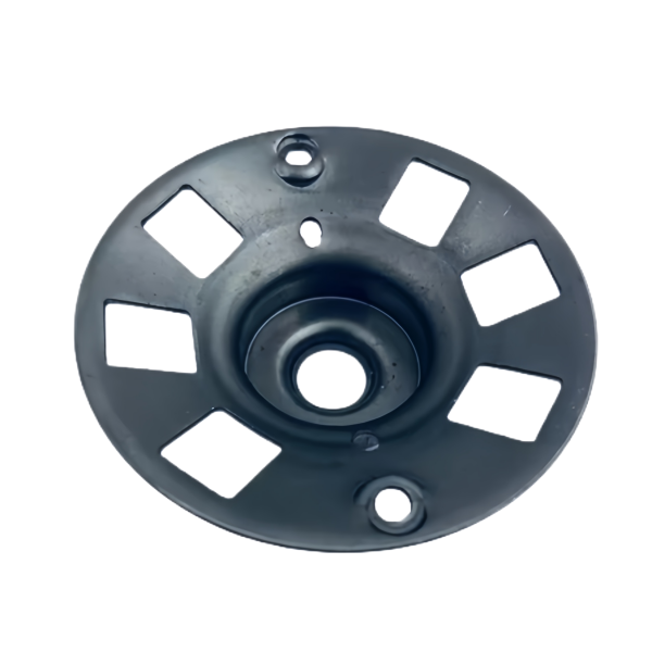
The Steel Deep Drawn Flange Plate with Center Hub is a flat plate with a tubular hub raised out of its centre, and the whole point is that the hub and the flange are one piece of steel with no weld to leak or fatigue. The tension in this part is keeping the wide flange dead flat while you simultaneously push metal up into a hub, and the engineering below is about drawing the hub without cupping the face.
Drawing the central hub up from a flat flange
A flange-and-hub part starts as a flat blank – 80 mm diameter, 4 mm thick DC01 – and the hub is drawn up from the centre rather than machined from a thick plate, because drawing gives a grain flow that follows the hub wall and resists the pull-out loads a machined hub would see across cut grain. We draw the hub in one stage to 30 mm outside diameter and 20 mm height, with the flange left as the unused rim of the blank. The draw reduction at the hub is about 35 percent, kept there so the flange does not get pulled into a crown as the hub rises.
The punch that forms the hub has a generous 6 mm corner radius at the flange-to-hub junction, because that is where the steel must flow from the flange into the hub wall. Closing that radius to save flange width cracks the junction on every part; the radius is what lets the flange stay flat while the hub grows.
- 80 mm blank, 4 mm DC01; hub drawn to 30 mm OD, 20 mm high in one stage.
- Hub draw reduction ~35 percent so the flange stays flat.
- 6 mm junction radius lets flange metal flow into the hub wall.
The central island that the hub is drawn from is sized to about 45 mm diameter – large enough to feed the 30 mm hub wall without starving the junction, small enough that the surrounding flange is fully clamped and cannot follow. We learned the hard way that an island sized like the hub itself lets the flange pucker just outside the junction, so we keep the island at least 1.5x the hub diameter. The blank thickness of 4 mm is chosen so the hub wall finishes near 3.6 mm after the draw, leaving enough to machine the bore without breaking through.
Keeping the flange face flat while the hub is formed
The flange is the sealing or bolting face, so it must stay flat to within 0.05 mm even as the hub is drawn from its centre. We hold it by clamping the flange hard through the hub draw and by drawing the hub from a central island of stock rather than from the whole blank, so the flange material is constrained and cannot follow the hub upward. After drawing we restrike the flange face 0.1 mm to kill any residual crown from the clamp release.
Flange flatness is measured on a surface plate with a 0.05 mm feeler at first article and then checked with a go/no-go flat gauge in production. A flange that crowns by 0.1 mm will not seal on a gasket and will rock on a bolt circle, so we treat flatness as a machined feature even though the part is drawn.
- Clamp the flange hard; draw the hub from a central island so the flange is constrained.
- Restrike the flange face 0.1 mm to remove the clamp-release crown.
- Gauge flange flatness to 0.05 mm every run; surface-plate it on first article.
Steel grade and finish for a flanged hub plate
DC01 is the default for a flange-and-hub because it draws the hub in one stage and takes zinc or e-coat without prep trouble. Where the hub carries a pressed-in bearing or sees weather we move to DC04 for the slightly better draw behaviour at the junction, or to a zinc-coated base stock so the hub bore edge is protected after machining. We avoid high-carbon steels because they crack at the junction radius no matter how open we make it.
Finish is tied to the flange face. A plated finish at 8-12 microns covers the flange and the hub bore edge; e-coat at 15-20 microns is our choice where the part sees salt spray because it throws into the hub corner better than powder. We mask the hub bore during coating when the bore is machined to a press fit, because coating inside a press-fit bore is the fastest way to get a bearing that will not seat.
- DC01 default; DC04 or Z-base where the hub is loaded or weathered.
- Plate 8-12 microns or e-coat 15-20 microns for salt spray.
- Mask the hub bore during coating when it is a press fit.
Controlling hub bore and flange bolt-circle position
The hub bore is the functional diameter – it carries a shaft, a bearing or a pressed sleeve – so it is machined after drawing to +/-0.03 mm and held round within 0.03 mm TIR. The flange bolt circle is the locating feature, with six M5 holes on a 65 mm pitch-circle diameter held to +/-0.1 mm and the holes square to the flange face within 0.1 mm. We machine the bore and drill the bolt circle in one set-up indicated off the flange face, so the bore is automatically square to the bolt circle instead of relying on the drawn face.
Bolt-hole position is gauged with a pin plate every run and CMM-checked at first article, because a 0.2 mm drift in the pitch circle is a flange that will not line up with its mating part. The hub bore is air-gauged in production because a bore that goes 0.05 mm out of round at the junction is the hidden cause of a bearing that spins in its seat.
- Hub bore machined to +/-0.03 mm, round 0.03 mm TIR, after drawing.
- Six M5 holes on 65 mm PCD, position +/-0.1 mm, square to face 0.1 mm.
- Machine bore and bolt circle in one set-up off the flange face.
The bore is bored and the bolt circle drilled on a CNC machining centre indicated off the finished flange face, never off the drawn blank edge, because the drawn face can sit 0.1 mm off the blank centre after the hub draw and indicating off it would throw the bore out of square to the bolt circle by that amount. We hold the bore-to-flange squareness to 0.05 mm over the 20 mm hub height, which is what lets a bearing or sleeve press in straight instead of cocking on the first 5 mm of engagement.
Where a flange hub cracks at the shoulder and why
The failure that defines this part is a crack at the flange-to-hub shoulder, and it has two causes we design out at the quote. A shoulder radius that is too tight concentrates the draw strain and the junction necks and cracks – we open it to the 6 mm called out above and never let tool wear close it below 5 mm. The second cause is a flange that was not clamped hard enough, so the flange material fed into the hub unevenly and the shoulder thinned on one side; this shows as a crack on one side only and is fixed by raising the clamp load, not by changing the steel.
We keep a cracked sample on the reference board so the operator tells the two apart: a full-circumference crack is a radius problem, a one-sided crack is a clamp problem. A hub that cracks at the shoulder in service lets the flange separate from the hub under load, which is a catastrophic failure we will not ship.
- Open the shoulder radius to 6 mm; redress the punch before wear closes it to 5 mm.
- Raise the blank clamp if a one-sided shoulder crack appears.
- Match any shoulder crack to the reference board before changing the tool.
How we verify a flange plate with center hub
A flange-and-hub plate is verified at first article for the features that carry load – flange flatness, hub bore and bolt-circle position – and then gauged for those same features in production because the draw is stable once the clamp and radius are set.
- First article: surface-plate flange flatness, CMM on hub bore roundness and diameter, bolt-circle position and squareness, plus a material certificate.
- Production: flat go/no-go gauge on the flange every run, pin plate on the bolt circle, air gauge on the hub bore, and a visual on the shoulder for cracks on the first and last part.
- Shipment file: dimensional report, coating thickness, and material cert travel under your part number.
The draw die and the machining fixture are built and held in our own toolroom against your part number, with the shoulder radius and clamp load archived so a reorder reproduces a flat flange and a sound shoulder. A reorder is a draw, a machine pass and a gauge check, not a new development.
Draw ratio, wall thinning, radii and trim — the design decisions behind a part like this are worked through with numbers in our deep drawn covers guide, and the Precision Deep Drawn Parts pages collect the rest of the family.
Specifications
| Item | Steel Deep Drawn Flange Plate with Center Hub |
|---|---|
| Brand | AUNOV |
| Designing | Send drawings, or send a sample to be measured, DFM feedback is returned with the quote. |
| Tooling | Dies designed and built in our own toolroom, with your part number on the tool record. |
| Samples | Samples for approval come with a full dimensional report and material certification. |
| Materials | Carbon steel (SPCC / DC01) leads the stock list for this part, alongside 304 / 316 stainless steel, aluminium, brass and copper, and the grade is fixed at the drawing review. |
| Surface finish | Zinc, nickel or chrome plating, e-coat, powder coat, anodising or passivation, per your print. |
| Processing | Staged deep drawing with in-line annealing where needed, then pierced and machined in house. |
| Equipment | Mechanical presses 5-250 T and hydraulic presses 250-500 T, CNC turning centres and a climate-controlled CMM room. |
| Tolerance | Tolerances to +/-0.1 mm as drawn, +/-0.03 mm after machining. |
| Delivery terms | Standard terms FOB, DDP offered to EU and US, T/T or L/C, D/P on repeat business, call-off schedules supported. |
Frequently Asked Questions
Why draw the hub instead of machining it from thick plate?
Drawing gives a grain flow that follows the hub wall, and that flow resists the pull-out loads the part sees in service. A hub machined from plate is loaded across cut grain, which is the weaker direction for exactly this kind of load.
Why does the junction between flange and hub need such a generous radius?
Because that is where the steel has to flow from the flange into the hub wall. A generous radius at the junction is what lets the flange stay flat while the hub grows, and closing it to win back flange width cracks the junction on every part.
How do you keep the flange flat while the hub is formed?
The draw reduction is set so the flange is not dragged into a crown as the hub rises. Hub height, reduction and junction radius are decided together, because changing one to improve another usually shows up as either a crowned flange or a cracked shoulder.
Where does a flange-and-hub part fail, and how is it checked?
At the shoulder where the flange turns into the hub, when the radius is closed down or the reduction is pushed past what the material will take. The first article is checked at the junction along with hub bore and flange bolt-circle position, so the failure mode is caught before the run is released.
Related Products



Request a Quote for This Part
Send a drawing or sketch — get material advice, tooling cost and a per-piece price within 24 hours (working days).