
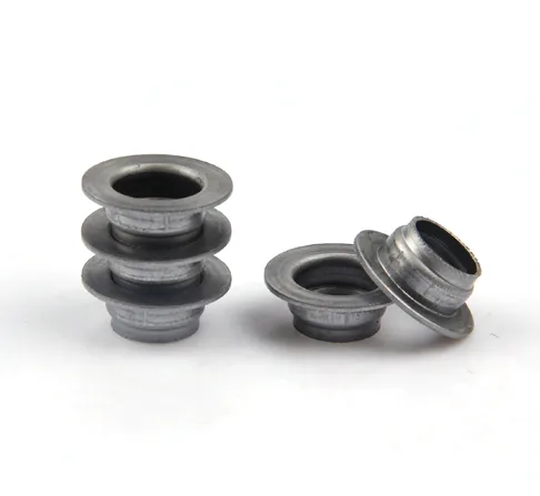
A deep drawn bushing is one part doing three jobs
A stainless steel deep drawn bushing is a cylindrical sleeve – a plain bearing surface, a guide, and a spacer – formed from flat sheet in a drawing operation rather than cut from bar or turned from tube. It carries a shaft, a pin, a bolt, or another tube; it sets the distance between two faces; and it absorbs the wear that would otherwise land directly on the housing. One part, one material, no seam, no joint, nothing to assemble.
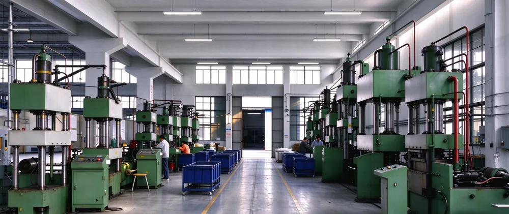
We coil-blank and progressively draw, coining on the final station where the print calls for it, with every stage logged against your part number, on 5-250 T mechanical presses, 250-500 T hydraulic presses and annealing furnaces in line, and first articles and batch samples checked on the CMM. Flange and rim dimensions to +/-0.05 mm with wall controlled by the draw, and critical dimensions carrying CMM data with the shipment. Materials held include carbon steel, 304 and 316 stainless steel, aluminium and brass, with mill certificates and heat numbers accompanying the first article. This page is about what deep drawing gives a bushing that machining does not – and where the process itself sets the limits you have to design around.
Why the bushing family suits deep drawing
A bushing is a cup with the bottom idea removed: a straight or stepped wall, an inside diameter that becomes the bearing surface, and often a flange that locates the part in its housing. That geometry is close to the ideal case for drawing, and four things follow from it:
- The wall is seamless. A drawn bushing has no weld seam and no split line, so there is no seam to distort under press-fit, no seam to leak past, and no flat spot where a rolled-and-welded tube would have its bead. For a bearing surface this matters more than for almost any other drawn shape – the inside diameter is the working surface and it has to be uniform all the way round.
- The grain flows with the part. Drawing elongates the grain structure along the wall instead of cutting across it, which raises the bushing’s strength and its resistance to cracking along the axis. A turned bushing machined from bar stock has grain running across the load path at the ends.
- The flange, the rim, and the stepped features come out of the same hit. A locating flange, a countersink, a shouldered end or a knurl can all be formed in the progressive die instead of being second-operation machined. On a bushing with a mounting flange, that typically removes an entire turning operation.
- Material usage is the sheet thickness, not the bar diameter. A bushing with a 1 mm wall uses 1 mm sheet whether its outside diameter is 8 mm or 60 mm. The same part cut from bar removes most of what it pays for as swarf – and the cost gap widens as the diameter grows.
The honest limit is the other side of the same coin: deep drawing is a volume process with a tooling lead time. For a handful of prototypes, a turned or machined bushing will be in your hand first. Past a few thousand pieces, with the drawing stable, the drawn bushing is the cheaper and usually the better part.
The drawing sequence, station by station
A bushing looks simple, which is why the process behind it is worth spelling out. What happens between the coil and the bin:
| Blanking | The coil is blanked into a disc sized to the finished outside diameter plus draw allowance. Blank diameter is the first calculation – too small and the wall thins past the print, too large and the press tonnage and the trimming allowance both grow. |
|---|---|
| Drawing | The disc is drawn into a cup on the first station, then progressively deeper on the following stations. Each station reduces the diameter and increases the height in controlled steps rather than one aggressive hit, which is what keeps the wall from thinning unevenly. |
| Ironing or sizing | Where the print calls for a controlled wall thickness or a finished inside diameter, the cup passes an ironing station that thins and sizes the wall against a mandrel. This is also the station that produces a smooth, uniform bearing surface on the inside. |
| Flange and feature forming | The locating flange, any countersink, the shoulder, or a mounting hole is formed in the progressive die. Because these features come out of the same die as the cup, they stay concentric with the bore without a second setup. |
| Trimming | The drawn edge is trimmed to length and to the print’s flange diameter. Trimming after drawing is standard practice because the as-drawn edge is neither straight nor uniform. |
| Annealing | Work hardening accumulates through the stations, and deep cups are annealed in line between draw stages to restore ductility before the next reduction. Stainless steel in particular hardens fast, and skipping the anneal shows up as splitting at the wall. |
| Deburring and finishing | Edges are deburred, and the part is passivated or finished to the print. On a bushing this is not cosmetic – a burr on the bore scores the shaft it is meant to guide, and a burr on the mounting face keeps the part from seating square. |
Every one of those stages is logged against your part number, so a bushing delivered six months after the first article can be traced back to the same press setup, the same die condition, and the same coil.
Choosing the stainless steel: 304, 316, 303, 17-4 PH
Most drawn stainless steel bushings are 304 or 316, and the choice is usually decided by corrosion, magnetism, or strength – in that order:
| 304 | The default. Good corrosion resistance, good forming behaviour in the press, and the widest availability in coil. Austenitic, so essentially non-magnetic as drawn. Right for most indoor, most washdown, and most general engineering applications. |
|---|---|
| 316 | Adds molybdenum, which buys resistance to chlorides and to most chemical media. The right call for marine, coastal, road-salt, or any wet chloride environment. Draws slightly harder than 304 and costs more per kilo, so it is specified where the environment earns it rather than by habit. |
| 303 | A free-machining grade with sulphur added. Excellent when the bushing needs extensive secondary machining – a threaded bore, a cross-drilled hole – but the sulphur inclusions reduce corrosion resistance and ductility, so it is a poor choice for a deeply drawn wall. |
| 17-4 PH | A precipitation-hardening grade. Drawn in the soft condition and then age-hardened to high strength, it suits bushings that carry load or wear in a compact envelope. The extra heat treatment step has to be planned into the route, and it adds cost. |
Mill certificates and heat numbers accompany the first article whichever grade you choose, so the material in the shipped bushings is traceable to the coil it came from. If the application genuinely needs carbon steel, aluminium, or brass, we hold those too – but a stainless steel bushing is usually chosen precisely because the environment is the problem.
Wall thickness and draw ratio: the limits the process sets
Two numbers decide whether a bushing can be drawn at all, and both belong on the drawing review rather than in the toolroom’s problem list:
- Draw ratio per station. Each station can reduce the diameter by a limited amount before the wall thins past acceptable limits or the cup wrinkles. For stainless steel that limit is typically a reduction of around 20-25% per station, which is why a deep bushing takes several stations with an anneal between them rather than one hit. The total reduction from blank to finished cup is the sum of those steps, and it is what sets how many stations – and how much tonnage – the die needs.
- Wall thickness relative to diameter. Thin walls on large diameters are the hard case: the wall has to resist the blankholder pressure without wrinkling and the ironing pressure without splitting. As a rule of thumb, wall thickness below roughly 1% of the outside diameter moves the part from routine into engineering. Above about 5% the part stops behaving like a drawn cup and starts behaving like something that should be machined.
Two more process realities that show up on the print: earing – the slight waviness at the drawn edge caused by the coil’s directional properties, which is why trimming comes after drawing – and thinning at the wall, which is deepest partway between the nose radius and the flange. If a bushing has a minimum wall callout, it should say where on the part it applies, because the thinnest point is predictable and it is not where most people assume.
Tolerances: what “controlled by the draw” means on a bushing
Drawing controls some dimensions very well and others only approximately, and knowing which is which keeps a drawing honest:
| Inside diameter | Held by the punch or the mandrel, so it is one of the better-controlled dimensions – typically within a few hundredths on a bushing in this size range. On an ironed bushing it is the most consistent dimension on the part. |
|---|---|
| Wall thickness | Controlled by the gap between punch and die. It varies with the thinning pattern described above, so a uniform-wall callout needs to state whether it is a nominal or a minimum. |
| Outside diameter and flange diameter | Set by the die and the trim. These are the dimensions that carry the +/-0.05 mm band, along with flange and rim features that locate the part in its housing. |
| Concentricity | Bore to outside diameter, and bore to flange. Formed in one setup in the progressive die, which is what keeps it tight – but it is still a real tolerance and it matters on any bushing that has to run true on a shaft. |
| Length and squareness | Length is a trim dimension and is the least tightly controlled of the set. Squareness of the trimmed end to the bore depends on how the part is supported at trim, and it is worth a note on the drawing when the bushing has to seat against a face. |
First articles and batch samples are checked on the CMM, and critical dimensions carry CMM data with the shipment. On a bushing, “critical” usually means the bore, the concentricity, and whatever locates the part in the housing – it is worth naming those three explicitly on the drawing rather than leaving the inspection plan to interpretation.
Surface finish and deburring
The inside diameter of a bushing is a bearing surface, and its finish is a functional requirement rather than a cosmetic one. Three points that decide whether the part performs:
- Bore finish. An ironed bore comes off the process smooth and uniform; an unironed drawn bore carries the tool marks of the punch. Where the shaft runs against the bushing, the drawing should state a surface roughness target – Ra 0.8 µm is a common requirement for a plain bearing surface – and whether it applies to the bore specifically.
- Burr-free edges. A burr on the bore scores the shaft; a burr on the mounting face stops the part seating square and turns a flat interface into a three-point one. Deburring is part of our route on every bushing, and it is one of the cheapest requirements to state and one of the most expensive to discover late.
- Passivation. Stainless steel is only corrosion-resistant because of its chromium oxide layer, and drawing, trimming and handling all disturb it. Passivation after forming restores it and is standard on any stainless steel bushing that will see a wet or corrosive environment. It should be stated as a requirement, not assumed.
Deep drawn, machined, or turned: which bushing, when
The same bushing can often be made three ways, and the differences are worth putting side by side:
| Deep drawn | Seamless wall, grain following the part, flange and features in the die, material cost close to the sheet cost. Best at volume, and best whenever the wall is thin relative to the diameter. Tooling lead time is the entry cost. |
|---|---|
| Machined from bar | Any geometry, any alloy, no tooling. The wall is cut across the grain and there is a seam if the part is made in two pieces. Best for prototypes, for large diameters with thick walls, and for quantities too small to amortise a die. |
| Turned from tube | Faster than machining from bar for thin-wall parts, and the wall is seamless – but the tube itself was made by drawing or welding, so a welded tube puts a seam back into the part. A sensible middle route for medium quantities. |
The crossover is usually a few thousand parts with a stable drawing. Below it, machining wins on lead time. Above it, drawing wins on unit cost and on the seamless wall – and for a bearing surface, the seamless wall is not a detail.
Where stainless steel deep drawn bushings end up
The part shows up wherever a shaft, pin, or tube has to be guided, spaced, or protected by something that will not rust:
- Valves and fluid handling – guide bushings around stems and spindles, where 316 earns its cost through constant contact with the medium.
- Automotive and heavy vehicle – pivot and king-pin bushings, cable guides, and spacer sleeves, usually 304, in volumes that suit the process.
- Electrical and electronic enclosures – bushings that carry a shaft, a lever, or a cable through a panel, combining a bearing bore with a mounting flange in one part.
- Fasteners and hardware – flanged bushings, sleeves with a rolled rim, and shouldered spacers that a weld nut or a pressed insert would otherwise do.
- Medical and laboratory equipment – small-bore 316 and 17-4 PH bushings where corrosion resistance and a clean, burr-free surface are both specified.
Drawing and ordering it
Every stage is logged against your part number, mill certificates and heat numbers accompany the first article, and critical dimensions carry CMM data with the shipment. The drawing review is where a bushing is won or lost, and these are the things most often missing:
- Which dimensions are functional. The bore, the concentricity, and the locating faces are what the bushing does. Mark them critical; leave the rest to standard tolerance.
- Wall thickness, and where it is measured. Nominal or minimum, and at which station along the length, because the thinnest point is predictable.
- Bore finish, as a roughness target. Ra value and the surface it applies to, if the bore carries a shaft.
- The material grade and its condition. 304, 316, 303, or 17-4 PH – and for the hardening grades, the heat treatment condition.
- Concentricity callouts. Bore to outside diameter, and bore to flange, with the tolerance band stated.
- Squareness of the trimmed end, if the bushing seats against a face.
- Burr direction and edge break, at the bore, the mounting face, and the trimmed end – three different edges, three different requirements.
- Passivation or other finishing, and any surfaces that must be masked.
Our deep drawn covers guide puts numbers to the design decisions behind a part like this — draw ratio, wall thinning, radii and trim; the Precision Deep Drawn Parts pages collect the rest of the family.
Specifications
| Item | Stainless Steel Deep Drawn Bushing |
|---|---|
| Brand | AUNOV |
| Designing | Quotation reflects the real drawing: tolerances, finish and features are priced as specified. |
| Tooling | Our toolroom covers die design, wire-cut EDM and maintenance, so a die can be re-cut against the approved drawing, and the charge is refundable against agreed volumes. |
| Samples | Prototype and pre-production samples are provided against the drawing, so the sample is retained as the master, and production starts only after your written sign-off. |
| Materials | Materials held include carbon steel, 304 / 316 stainless steel, aluminium and brass; mill certificates and heat numbers accompany the first article. |
| Surface finish | Plating, coating, anodising or passivation are chosen from the drawing; masking and laser marking are available where the job needs them. |
| Processing | Coil blanking and progressive drawing, coining on the final station where the print calls for it; every stage is logged against your part number. |
| Equipment | 5-250 T mechanical presses, 250-500 T hydraulic presses and annealing furnaces in line; first articles and batch samples are checked on the CMM. |
| Tolerance | +/-0.05 mm on flange and rim dimensions, wall controlled by the draw; critical dimensions carry CMM data with the shipment. |
| Delivery terms | CIF or DDP, with FOB available, payment by T/T, L/C at sight or D/P; call-off schedules are supported. |
Frequently Asked Questions
What is the difference between a deep drawn bushing and a machined bushing?
A deep drawn bushing is formed from flat sheet in a progressive die, so the wall has no seam and the grain runs along the length of the part; a machined bushing is turned or bored from bar stock, where the grain crosses the load path at the ends. For a plain bearing surface the seamless drawn wall is the stronger and cheaper choice past a few thousand pieces, because the locating flange, rim, and steps all come out of the same hit rather than a second turning operation. Below that volume a turned bushing is in your hand sooner.
What wall thickness and tolerances can a stainless steel deep drawn bushing hold?
On a stainless steel bushing we hold flange and outside-diameter features to about +/-0.05 mm, with the bore set by the punch or mandrel on an ironing station and verified on the CMM. Wall thickness is governed by the punch-to-die gap and varies through the draw, so a uniform-wall callout should state whether it is nominal or minimum. As a rule, wall below roughly 1% of the outside diameter moves the part into engineering review, and above about 5% it begins to behave like a machined component rather than a drawn cup.
Which stainless steel grade is best for a deep drawn bushing?
Most drawn stainless steel bushings are 304 or 316. 304 is the default for general indoor and washdown use; 316 adds molybdenum for chloride and marine exposure. 303 machines well but draws poorly because of its sulphur content, and 17-4 PH is drawn soft then age-hardened for high load in a compact envelope. Mill certificates and heat numbers accompany the first article whichever grade you specify, so the material in the shipped bushings traces back to the coil.
What is the minimum order quantity and lead time for drawn bushings?
Production runs start at 1,000 pieces, with tooling made in-house so the die matches your print instead of a catalogue size. We return a quote within 24 hours of receiving the drawing, and first articles are measured on the CMM before the full run begins. Every stage is logged against your part number, so a bushing delivered months later can be traced to the same press setup, die condition, and coil.
Related Products



Request a Quote for This Part
Send a drawing or sketch — get material advice, tooling cost and a per-piece price within 24 hours (working days).