
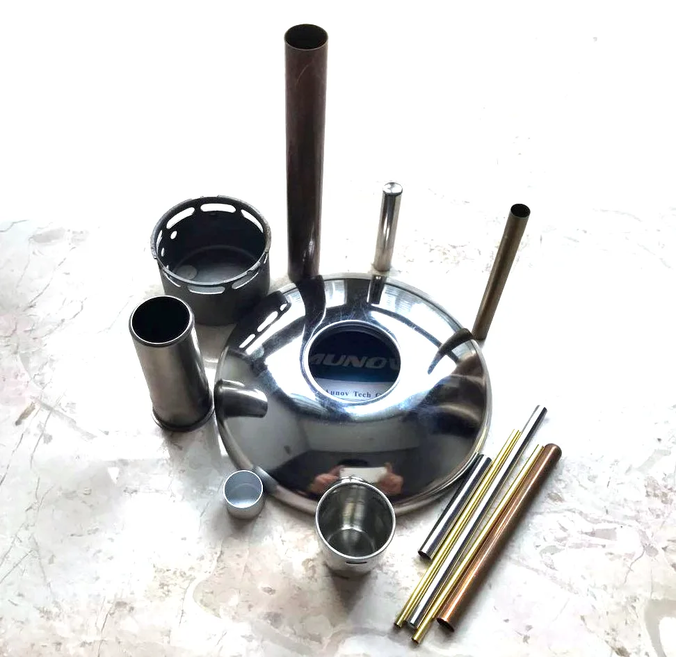
Dip brazing is a joining process with a whole design philosophy attached to it
A deep drawn and dip brazed aluminium arming box is assembled from drawn aluminium components and joined by immersing the whole assembly in a molten flux at a temperature below the aluminium’s melting point. That single process fact reshapes the entire design. It is not a way to join two parts that were already designed; it is a design method with its own rules, and a design that ignores those rules will be beautiful on the drawing and unmanufacturable in the furnace.
We deep draw from coil or blank with in-process annealing so walls thin evenly, and first articles verify the whole flow before the run is released, on mechanical presses from 5 to 250 T and hydraulic presses 250-500 T with in-line annealing furnaces, with first articles and batch samples checked on the CMM. General tolerance on drawn sections is +/-0.1 mm with +/-0.03 mm on machined seats, and capability is checked on the first article before the run continues. Standard stock is carbon steel in SPCC and DC01 grades, 304 and 316 stainless steel, aluminium and brass, with material substitutes proposed only with your written approval. Finish is selected from the drawing – plating, coating, anodising or passivation – with finish thickness and adhesion checked on the first article. This page is about what dip brazing demands of a design, and the four rules that govern everything.
Rule 1: the parts must be assembled before they are brazed
Dip brazing joins parts that are already in their final relative positions. This has a large and immediate consequence: any feature that cannot be reached or assembled before brazing cannot exist.
- A closed internal cavity cannot be inspected, filled, or drained. If the box has an internal chamber that needs to be cleaned, sealed, filled with something, or pressure tested, that has to happen with the box open – and then the box has to be brazed shut afterwards, which means the sealed cavity is never inspected after it is closed. This is a genuine limitation and it affects how the part is designed and how it is tested.
- Overlap flanges are the whole mechanism. A dip-brazed joint is made by two flanges that overlap, with a gap between them that flux and filler enter. The gap is filled by capillary action during the dip. So the joint is designed as a lap joint with a controlled gap, and the flange’s width, its thickness, its flatness, and its clearance to the mating flange are all design parameters.
- Clearance in the gap is critical. Too tight and the filler cannot enter and the joint does not fill; too loose and the filler drains out and the joint is incomplete. The gap is normally a small fraction of a millimetre and it is one of the most important dimensions on the whole assembly.
- Drainage holes and vent holes are mandatory features. Trapped air and trapped flux must be able to escape, and excess flux must be able to drain. A dip-brazed assembly without designed vent and drain holes will either not fill or will trap flux inside it forever.
Rule 2: the aluminium alloy is not a free choice
The filler metal and the parent alloys have to be compatible, and the selection is constrained in ways that are not intuitive:
| The filler | Usually an aluminium-silicon brazing alloy with a substantially lower melting point than the parent. It is not a structural member – it is a filler, and it is weaker than the parent. A joint’s strength is limited by the filler, and where a joint must be strong the joint must be designed with more overlap than seems necessary. |
|---|---|
| The parent alloys | Most wrought aluminium alloys are brazeable. Some are not – alloys containing certain elements that form unwanted intermetallics at the brazing temperature cannot be used, and this is a real limitation. Where a part needs high strength, the strength alloy and the brazeability requirement frequently conflict, and the resolution is a two-material design where the structural member is a different alloy or a different material from the brazed shell. |
| Cladding | A common solution is to clad the brazing surface. A sheet with a thin brazing-alloy layer on one face can be formed and joined like a normal aluminium sheet and braze beautifully, and this is how many production brazed aluminium housings are made. It is a material choice that has to be made at purchase, not a process choice made later. |
| Silicon and magnesium | Silicon improves brazeability and reduces the surface tension that resists filler flow. Magnesium raises strength but is aggressive to some fluxes and to some filler choices. These trade-offs are the substance of an alloy selection and they are worth a conversation with the process engineer rather than a guess. |
Rule 3: the joint is designed for the filler, not for the parent
Three design features that follow, and that are not standard sheet-metal practice:
- The overlapping flanges must be flat and parallel. The filler’s path is a capillary, and a gap that varies along the joint fills unevenly. The flange’s flatness on a dip-brazed assembly is therefore a functional requirement, and it is a requirement on both mating flanges – the joint’s flatness is the pair’s flatness.
- The flanges need sufficient width. The joint’s strength grows with overlap length, and where a joint must carry load the overlap has to be generous. On a box, the flanges are usually inward-returning lips around the whole perimeter, and their width is a structural parameter.
- The brazing must not distort the box.>An aluminium box is thin-walled and heat-sensitive. In the furnace, the assembly heats uniformly in the ideal case, but in practice the mass distribution matters: a heavy boss and a thin wall heat at different rates, and the part distorts. This is why a dip-brazed box’s design needs uniform section thickness wherever possible, and why heavy features are often kept away from thin panels.
Rule 4: what survives the furnace
Two things to check on any feature that goes through a dip brazing cycle:
- Any elastomer, plastic, bearing, or plated surface will be destroyed. The cycle is typically several hundred degrees with a molten salt flux. Seals, O-rings, gaskets, plastic inserts, chrome plating, cadmium plating, and anything with a melting point below the brazing temperature cannot be in the assembly during brazing. Where a seal is needed, it is fitted afterwards, and where a plated surface is needed it is plated afterwards. This is a hard constraint and it drives the assembly sequence.
- Tolerance and distortion after cooling. The part comes out of the furnace changed. Flatness moves, and the dimensional band on a dip-brazed assembly is wider than on the same part made by other means. This is why the stated tolerance structure distinguishes drawn sections at a general band from machined seats at a tight band – and why the tight band belongs to features that are machined after brazing, not before.
Geometry: an arming box, specifically
An arming box – a box associated with arming or firing systems in a defence or ordnance application – has additional requirements beyond being a brazed aluminium box, and they are worth stating plainly because they are the reason the process is used at all:
- Hermeticity or near-hermeticity. A brazed joint, properly designed, is hermetic. That is often the primary reason dip brazing is chosen over a bolted or a welded assembly – a brazed box can be sealed to a very low leak rate without a gasket, and the seal will not degrade in the way an elastomer seal does.
- Environmental endurance. A defence application implies temperature extremes, vibration, humidity, and possibly salt exposure. Aluminium’s corrosion resistance is a benefit, and the absence of an elastomer seal in a hermetic joint is a significant benefit in a temperature extreme where a seal would have gone hard or soft.
- Long service life. A brazed joint has no moving parts and no elastomer to age. Where a service life of decades is required, a brazed assembly is a genuinely good answer and this is a design argument as much as an economic one.
- EMI, where relevant. A fully brazed aluminium enclosure is an excellent electromagnetic shield, because there is no seam in the electrical sense. Where a box has to be an EMI shield, dip brazing gives a continuous conductive shell with no gasket to degrade the contact.
A dip-brazed assembly’s practical answer is one alloy throughout
Standard stock is carbon steel in SPCC and DC01 grades, 304 and 316 stainless steel, aluminium and brass, with material substitutes proposed only with your written approval. On a dip-brazed assembly the practical answer is almost always aluminium, and the note about substitutions is really a note about why substitution is restricted here – a steel component in a brazing assembly is either impossible or requires a completely different joining method for that joint.
Finish is selected from the drawing – plating, coating, anodising or passivation – with finish thickness and adhesion checked on the first article. Three requirements on a brazed part:
- Finishing is after brazing. Nothing is plated or anodised before the furnace, so the finish is a downstream operation and the part must be designed to be handled and fixtured after brazing.
- Anodising is the natural finish for a brazed aluminium box: it is hard, cleanable, corrosion-resistant, and dimensionally very well behaved. It is also the finish that would be specified on a defence or ordnance-adjacent part for its wear and corrosion performance.
- Mask any feature that must stay bare – a machined seat, a ground pad, a thread, a sealing face, an electrical contact. On a brazed part the masking is a post-braze operation and it should be on the drawing.
Dip brazing is a design philosophy, not a joining method
Eight things, and the first three exist only because of the brazing process:
- Every joint, identified as a lap joint, with the flange’s overlap width, the gap dimension, and the tolerance on both. This is the most important thing on a dip-brazed drawing and it is the one most often left to the process engineer.
- Vent and drain hole positions and sizes, which are mandatory features and are rarely drawn.
- Which features are fitted after brazing – seals, inserts, threaded items, anything plated – because this fixes the assembly sequence.
- The alloy and the filler, confirmed in writing, and whether a clad sheet is used.
- Flatness of every mating flange pair, and the general dimensional band after brazing rather than before.
- The leak or hermeticity requirement, and how it is verified. This is what the whole process is for and it should be a stated requirement with a method.
- Wall thickness uniformity, particularly where a heavy feature is near a thin panel, because that is the distortion risk.
- Which surfaces are masked from the finish, and whether dimensions apply before or after it.
Does this part need to be dip brazed?
Does this part need to be dip brazed, or would a welded or a bolted assembly do the job? Dip brazing is the right answer where hermeticity, no gasket, long life, or a continuous EMI shield matters, and where the assembly cannot be welded. It is the wrong answer where cost dominates, where the box is small and simple, or where a mechanical fastener is actually wanted for serviceability. A welded aluminium assembly is cheaper and can be leak-tight with a continuous weld; a brazed one is generally more leak-tight, more repeatable on a small batch, and does not distort as much. It is worth establishing what the sealing requirement actually is, because that is what decides the process, and it is a much better question to ask before the design is frozen than to answer by default.
The engineering calls behind a part like this — draw ratio, wall thinning, radii and trim — each get worked examples in our deep drawn covers guide; the Precision Deep Drawn Parts pages gather the rest of the family.
Specifications
| Item | Deep Drawn and Dip Brazed Aluminum Arming Box |
|---|---|
| Brand | AUNOV |
| Designing | DFM feedback accompanies the quotation, so surprises are caught before the die is cut. |
| Tooling | Die design and toolmaking stay in house, so the die charge appears as its own quotation line, and maintenance is tracked against the part number. |
| Samples | Sample parts are measured and reported before submission, so the sample is retained as the master, and the signed sample is kept for future reorders. |
| Materials | Standard stock: carbon steel (SPCC / DC01), 304 / 316 stainless steel, aluminium, brass; material substitutes are proposed only with your written approval. |
| Surface finish | Zinc, nickel or chrome plating, anodising, passivation or e-coat; finish thickness and adhesion checked on the first article. |
| Processing | Deep drawing from coil or blank, with in-process annealing so walls thin evenly; first articles verify the whole flow before the run is released. |
| Equipment | Mechanical presses from 5 to 250 T and hydraulic presses 250-500 T, with in-line annealing furnaces; first articles and batch samples are checked on the CMM. |
| Tolerance | +/-0.1 mm general on drawn sections, +/-0.03 mm on machined seats; capability is checked on the first article before the run continues. |
| Delivery terms | FOB Ningbo or Shanghai, T/T or L/C, with D/P accepted on repeat business; sea or air freight is quoted to your door. |
Related Products


Frequently Asked Questions
Why must dip brazing be designed in rather than added at assembly?
Because the whole assembly is immersed in molten flux below the aluminium’s melting point, so joint design, drainage and thermal mass have to exist from the first drawing. A part designed as if it were welded will trap flux or distort in the furnace.
What tolerances does AUNOV hold on the arming box?
General tolerance on drawn sections is +/-0.1 mm with +/-0.03 mm on machined seats, and capability is checked on the first article before the run continues.
Which materials can the arming box be made from?
Carbon steel in SPCC and DC01 grades, 304 and 316 stainless steel, aluminium and brass, with material substitutes proposed only with your written approval.
How is the finish controlled on the assembly?
Finish is selected from the drawing – plating, coating, anodising or passivation – with finish thickness and adhesion checked on the first article.
Request a Quote for This Part
Send a drawing or sketch — get material advice, tooling cost and a per-piece price within 24 hours (working days).