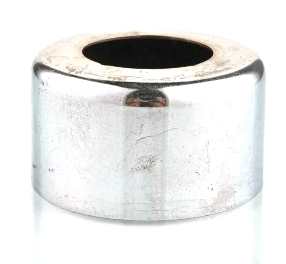
A pressure vessel can is a certified pressure boundary, and that changes what the drawing owes
A nickel-plated deep drawn pressure vessel can is the only part in this entire family that may be a regulated pressure component. That single fact changes the character of everything about it: the material becomes a controlled specification, the wall becomes a calculated one, the joints become qualified, and the documentation becomes part of the product. A general drawn can is specified by geometry and finish. A pressure can is specified by geometry, material, calculation, process qualification, and evidence – and the evidence is as much a deliverable as the metal.
We multi-stage draw with interstage annealing, trim and pierce in following dies, and every stage logged against your part number, on a press shop with 5-250 T mechanical and 250-500 T hydraulic presses with annealing ovens on site, CNC turning centres for secondary operations, and CMM inspection. Tolerance runs +/-0.05 mm to +/-0.1 mm across the part with wall thickness held to print, and critical dimensions carry CMM data with the shipment. Materials held include carbon steel, 304 and 316 stainless steel, aluminium and brass, with special grades sourced to the drawing when volumes justify. Zinc, nickel or chrome plating, anodising, passivation or e-coat, with the agreed finish travelling with the part number. This page is about what changes when a drawn part becomes a pressure boundary, and it assumes – correctly – that the first question at enquiry is which code applies.
Question 1: which code, and does the drawing have to say?
A pressure vessel can may fall under a pressure equipment directive, a pressure vessel code, a standard for the specific application, or – for very small volumes – a simpler regime. The consequences of which one applies are large:
| Material specification | A code usually specifies the material by grade and by standard, and often requires a specific product form. “Nickel-plated steel” does not identify a material. The base material has to be named by its specification, and its traceability becomes a requirement. |
|---|---|
| Design calculation | Codes specify allowable stresses, joint efficiencies, and design factors. The wall thickness is an output of a calculation, not a choice – and the calculation has to exist and be available for inspection. |
| Weld and joint qualification | Where there is a welded seam, the welding procedure and the welder’s qualification may need to be controlled and recorded. A drawn can with a closed seam has a weld that is part of the pressure boundary, and this is not optional. |
| Testing and evidence | Codes commonly require a pressure test, and increasingly require it to be documented. On a batch this means a test record per unit or per batch, and it means the test fixture and its method are part of the product. |
| Marking and traceability | Pressure equipment is often required to be marked, and to be traceable to its material. On a small can this may be a stamped or marked identifier on the part, and it is a real production requirement. |
So the very first thing a drawing for a pressure can should carry is which code or standard it is designed to, and if none, a statement of the design pressure, the medium, and the intended duty. Without that, the drawing cannot be reviewed properly and the quotation cannot be honest about what compliance costs.
Wall thickness, which is now a calculation
Wall thickness held to print is stated, and on this part that statement has a different meaning. The wall is:
- Set by the pressure, the material’s allowable stress, and the geometry – a cylinder under internal pressure is the classic case, where the hoop stress governs and the wall requirement follows directly. Where the can has a domed end, the end’s stress is a different calculation and a domed end is far more efficient than a flat one.
- Measured at its thinnest point, which on a drawn can is at the punch nose and at the corners. The calculation is done on that wall, not on the nominal. This is the point at which a pressure can’s drawing and its calculation have to agree, and where a general tolerance on the wall is not acceptable.
- Subject to a joint efficiency factor if the can is welded. A seam is not as strong as the parent material, and codes account for this with a factor. A drawn can with a closed seam has a lower allowable wall than a seamless one for the same design pressure – which is a real commercial consequence of a drawn construction on a pressure duty.
- Corroded over the service life. Codes usually require a corrosion allowance, and a nickel-plated steel can in a corrosive service will lose wall over time. The allowance is part of the wall specification.
Nickel plating, and a decision that is not purely cosmetic
Nickel plating on a pressure can is unusual enough to warrant asking why, because the answer changes the design:
- If the plating is for corrosion resistance, then the base material’s corrosion behaviour and the plating’s integrity are both pressure-boundary requirements, and a pinhole in the plating is a corrosion initiation site on a part that is holding pressure. Zinc flake or a thicker plate is usually a better choice than a thin decorative nickel plate where corrosion is the driver.
- If the plating is for a surface requirement – a wetted part needing a specific surface, a non-galling finish, a hydrogen-diffusion barrier, or an appearance requirement – then it is a functional coating and its specification should say so.
- Plating on a pressure boundary has a thickness that consumes wall. The design has to know whether the nominal wall is before or after plating, and on a thin-wall pressure component that difference can matter.
- Hydrogen embrittlement. A nickel or zinc electroplate on a cold-worked steel can introduce hydrogen, and a drawn and formed pressure can is cold-worked. If the part is a high-strength or safety-critical component, this needs a stated baking requirement with a defined delay. This is a real failure mode on pressure equipment and it is not a rare one.
- Masking the seams and threads. A pressure can’s seam is part of the boundary and should not be coated; threads must be masked so the connection works.
Seams, and the drawn construction’s specific weakness
A drawn can has one seam, and it is a longitudinal seam where the blank’s edges were joined. On a pressure duty that seam is the part’s most important feature, and there are two ways it is made:
- Welded and pressure tested. A full-penetration weld, a qualified procedure, and a test. This is workable and it is a common approach, and the joint efficiency factor on the calculation reflects the weld’s quality.
- Brazed or joined without full penetration. On a pressure boundary this is generally not acceptable at design pressure, because the joint does not develop the parent material’s strength.
And the alternative construction, which is worth raising at review on almost every pressure can: spun or machined from solid. A seamless can has no seam to qualify, no joint efficiency factor to apply, and a wall that is uniform rather than thinned by a draw. It costs more per part and it is a slower process, and for a low-volume or high-pressure application it is frequently the more economical answer because it removes an entire category of risk. Where the volume is high, the drawn can with a qualified weld is the economical answer and the seam has to be treated as what it is – part of the pressure boundary.
The four prerequisites for everything else
Eight things, and on this part the first four are prerequisites for everything else:
- The applicable code or standard, or the design pressure, the medium, and the duty if none applies. This is the first line and the most important.
- The base material specification – grade, standard, and product form – confirmed in writing, with mill certificates and heat numbers.
- The design pressure, the design temperature, and the medium, including whether the medium is corrosive.
- Wall thickness with its tolerance, and the minimum wall location, agreeing with the calculation – not a general band.
- How the seam is made and how it is qualified, and whether the joint efficiency factor has been applied.
- The test requirement – pressure test, method, pressure, hold time, and whether it is per unit or per batch, plus who records it.
- Marking and traceability requirements, including whether the part must be marked with an identifier.
- Plating specification with its functional reason, its thickness, its holes’ acceptability, and any hydrogen embrittlement mitigation.
And the question that should be asked first
Does this part need to be a drawn part at all? On a pressure duty, the question is worth asking every time, because the drawn construction brings a seam, a joint efficiency factor, a thinning profile, and a cold-worked condition – and it brings those in exchange for cost and speed. A spun or machined can removes all four. The economics decide it, and the deciding factors are volume, pressure, and how much risk the application carries. On a low-volume, moderate-pressure, safety-relevant application, a seamless machined can is very often both cheaper overall and considerably more defensible. It is a conversation that costs nothing at enquiry stage and can save a great deal at qualification stage.
Not sure whether to draw, machine or weld this geometry? The guide to deep drawn covers compares the three routes and shows where each one wins; the full Precision Deep Drawn Parts range is linked from the overview page.
Specifications
| Item | Nickel-Plated Deep Drawn Pressure Vessel Can |
|---|---|
| Brand | AUNOV |
| Designing | Quotation follows the print, not a catalogue – a manufacturability review comes back with the quotation; the approved drawing is kept as the controlled master. |
| Tooling | Progressive and drawing dies are designed and built in house, so die cost stays transparent, and the die remains dedicated to your part. |
| Samples | Sample parts are measured and reported before submission, so the part is proven before it is made in volume, and the signed sample is kept for future reorders. |
| Materials | Materials held include carbon steel, 304 / 316 stainless steel, aluminium and brass; special grades are sourced to the drawing when volumes justify. |
| Surface finish | Zinc, nickel or chrome plating, anodising, passivation or e-coat; the agreed finish travels with the part number. |
| Processing | Multi-stage deep drawing with interstage annealing, trimmed and pierced in following dies; every stage is logged against your part number. |
| Equipment | Press shop running 5-250 T mechanical and 250-500 T hydraulic presses, annealing ovens on site, with CNC turning centres for secondary operations and CMM inspection. |
| Tolerance | +/-0.05 mm to +/-0.1 mm across the part, wall thickness held to print; critical dimensions carry CMM data with the shipment. |
| Delivery terms | FOB, CIF or DDP per Incoterms 2020, T/T with deposit and L/C for larger runs; price breaks tie to annual volume. |