
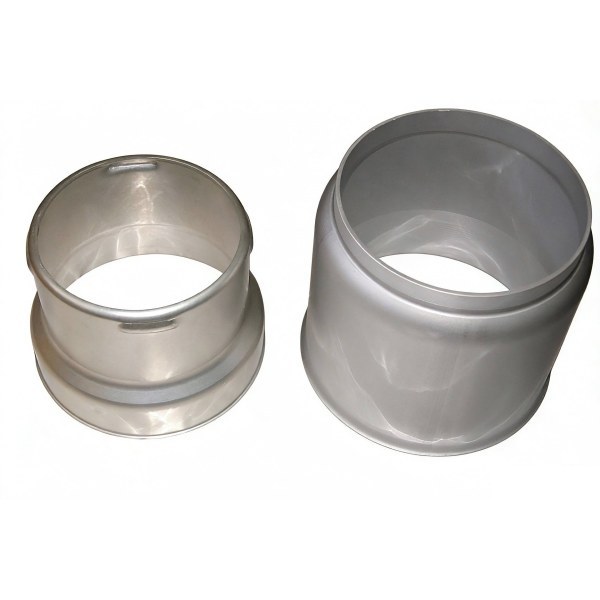
Large diameter changes which constraint wins
On a small drawn part the limiting factor is almost always the material’s ability to stretch without tearing, and the conversation is about draw ratio. On a large diameter duct the limiting factor is usually stiffness, and the conversation becomes about ovality, handling and support. The reason is geometric. Wall stiffness in a thin cylindrical shell falls with roughly the cube of the diameter for a given wall thickness, so a duct that feels rigid at 80 mm feels like foil at 300 mm even though both were formed from the same sheet.
The diameter to thickness ratio, usually written D over t, is the number that predicts which regime the part is in. Below about 100 the duct behaves like a stiff tube and can be handled, stacked and shipped with ordinary care. Between 100 and 250 it holds its shape under its own weight but deforms if it is gripped anywhere except at a formed end or a bead. Above 250 the part is a shell in the structural sense: it needs support during every operation after forming, and its free shape is no longer a reliable reference for inspection. A 300 mm duct in 1.2 mm aluminium sits at 250 and is right at the boundary, which is exactly where most real ducts live.
Ovality is a handling problem before it is a forming problem
The majority of out-of-round ducts that reach a customer were round when they left the press. They became oval in a basket, on a pallet, or in the hands of the person who took them out of the die. Because a thin shell has very little resistance to a diametral squeeze, a duct can be taken out of round by a single careless grip and will then stay out of round, because the material has yielded. That is the key point: at this D over t the deformation is not elastic, so the part does not spring back when the load is removed.
The controls that work are mechanical rather than procedural. A duct should leave the press into a cradle or a nest shaped to its outside diameter, not onto a flat surface. If it is stacked, it should be stacked with formed ends or purpose made separators carrying the load, never with duct on duct over the unsupported mid span. If it is gripped, the gripper should be a band or a collar at a stiffened location, not a two-finger clamp. And if the drawing permits a bead, a circumferential bead placed at the region where handling contact is inevitable turns a fragile area into a load carrying feature for almost no material cost.
- Specify roundness at the ends, where it interfaces, and allow a looser figure at mid span.
- Add a bead near any point where the part will be gripped or supported.
- Design the transport nest as part of the order, not as an afterthought.
- Inspect roundness after packing and unpacking once, on the first article, to see what the journey does to the part.
The wall thickness you can actually hold at this diameter
A large duct is not made in one draw. It is made in a sequence of draws, each one reducing the diameter by a fraction, with annealing inserted where the material needs it. Aluminium behaves more kindly than steel in this respect because it work hardens less steeply in the common ductile grades, but it also stretches less, so the per pass reduction is smaller. In practice a duct at this size is drawn through three to five stages, and the total reduction from blank to finished diameter is spread across them.
What arrives at the end is not a constant wall. The wall at the open end is close to the blank thickness; the wall at the closed end, where the material was stretched across the punch nose, is thinner by 10 to 20 percent. When the bottom is cut off to make a duct, that thinned material is usually removed, and what remains is a remarkably uniform wall. Where the closed end is retained, or where the duct carries a step or a neck, the thinned band is retained too and it is the thinnest point on the part. Any minimum wall callout should be checked at that band, and it should be measured by ultrasonic thickness gauge or by sectioning a sample, not inferred from a diameter measurement.
Aluminium adds one further wrinkle. Its thermal expansion coefficient is roughly twice that of steel, so a duct measured immediately after a forming or annealing operation will read larger than it will be at room temperature. If a duct is being measured hot, the reading is not the part’s dimension. Let it stabilise in the inspection room before the numbers are recorded, or the tolerance will be met on paper and missed in the assembly.
Ends: flanges, beads, rolled rims and rolled edges
The ends of a large duct do all the work. They interface with the adjoining part, they carry the handling loads, and they are the first thing to go out of round if anything does. There are four common end conditions and each has a different job.
- A plain cut end is the cheapest option and the least useful. It is acceptable only where the duct pushes into a compliant sleeve that will tolerate the cut edge and the ovality.
- A rolled rim or a hem folds the edge back on itself, which removes the sharp edge, adds a local stiffening ring, and doubles the wall thickness exactly where a hose clamp or a sleeve will bite. On aluminium it also removes the burr, which is the single most common cause of a cut sleeve.
- A circumferential bead immediately behind the end forms a positive stop for a hose or a sleeve and gives the clamp something to seat against. It is the standard answer where the joint must resist an axial pull off load.
- A formed flange, either a flat outward flange or a turned lip, gives a bolted or clamped face. A flange needs a flatness callout, because a wavy flange on a large duct will not seal no matter how hard the bolts are tightened.
Whichever end is chosen, it should be stated with a length from the end face and, where relevant, a radius. An end condition described only by its name leaves the toolmaker to invent the dimensions, and the invented dimensions will be whatever was convenient for the tool rather than what the assembly needs.
Aluminium or steel for a duct of this size
Aluminium is the default for large ducts because the weight penalty of steel grows quickly with size. The mass of a duct roughly scales with diameter times length times wall, so the difference between a 1.2 mm aluminium wall and a 1.0 mm steel wall that carries the same load is often a factor of three in part weight. That matters not only for the person lifting it but for the loads the fixing points see, because a duct hanging from four bolts transmits its own weight into whatever structure it is attached to.
Two aluminium specific issues need to be handled. The first is that aluminium has no endurance limit, so a duct that vibrates will eventually crack, whereas a steel duct may not. Where a duct sees flow induced vibration, the answer is to stiffen it with a bead or a flange near the excitation, not to thicken the whole wall. The second is galvanic corrosion at any interface with a dissimilar metal. A steel clamp on an aluminium duct is a galvanic couple, and the duct is the anode. Insulating washers or a stainless steel clamp with an insulating liner are the usual fixes, and the clamp should be named in the specification rather than left to the installer.
How we verify a large diameter duct before it ships
Large ducts are verified mostly for shape and straightness, because at this diameter the dimensional story is ovality, bow and end-squareness rather than a tight diameter number. The first article is mapped end to end; production is checked on a sampling plan with the critical shape features on every piece where the spec demands.
- Map ovality at several stations along the length, not just the ends, because a duct can be round at the lips and oval in the middle from handling.
- Check end-squareness and the flange or bead against the mating face; a duct that is round but skew at the end leaks at the joint.
- Confirm wall thickness ultrasonically at the thinnest drawn region and at any bead or roll.
- Straightness check over the full length on a flat or with a laser; bow is the defect that shows up only at installation.
- Internal surface inspection for draw marks or pickup that could shed or trap contaminants in service.
- File the shape map, wall report and material certificate under the part number.
Not sure whether to draw, machine or weld this geometry? The guide to deep drawn covers compares the three routes and shows where each one wins; the full Precision Deep Drawn Parts range is linked from the overview page.
Specifications
| Item | Aluminum Deep Drawn Large Diameter Tube Duct |
|---|---|
| Brand | AUNOV |
| Designing | Send the drawing, or a sample we can measure, a manufacturability review comes back with the quotation. |
| Tooling | Dies engineered and produced in our own toolroom, each die held against your part number. |
| Samples | Samples for approval come with a dimensional report and material certificate. |
| Materials | Aluminium leads the stock list for this part, alongside carbon steel (SPCC / DC01), 304 / 316 stainless steel, brass and copper, with the final grade confirmed at the drawing review. |
| Surface finish | Plating, e-coat, powder coating, anodising or passivation, per your print. |
| Processing | Multi-stage drawing, annealed in line where wall thinning calls for it, pierced and machined on the same floor. |
| Equipment | Press capacity from 5 to 500 T across mechanical and hydraulic lines, CNC turning centres, climate-controlled CMM room. |
| Tolerance | +/-0.1 mm on as-drawn features, with machined features to +/-0.03 mm. |
| Delivery terms | FOB standard, DDP offered for EU and US, payment T/T or L/C, D/P for repeat accounts, blanket orders and call-offs supported. |
Frequently Asked Questions
What limits a large diameter duct, draw ratio or stiffness?
Stiffness. Wall stiffness in a thin cylindrical shell falls with roughly the cube of the diameter for a given wall thickness, so the conversation stops being about how far the material can stretch and becomes about ovality, handling and support. The diameter-to-thickness ratio is the number that tells you which regime you are in.
How is ovality kept under control on a duct this thin?
Ovality is a handling problem before it is a forming problem. Below a ratio of about 100 the duct behaves like a stiff tube; between 100 and 250 it holds its own shape but deforms if it is gripped anywhere except a formed end or a bead; above 250 it needs support through every operation after forming.
Aluminium or steel for a duct of this size?
Aluminium where weight and corrosion resistance lead, steel where stiffness at an achievable thickness or raw material cost decides it. The choice interacts with the diameter-to-thickness ratio, because the lighter material may need a formed end or bead just to survive handling.
What end forms are available on a duct like this?
Formed flanges, beads, rolled rims and rolled edges. The ends earn their keep twice: they give you something to fix to, and once the duct leaves the press they are the only safe place to grip it.
Related Products


Request a Quote for This Part
Send a drawing or sketch — get material advice, tooling cost and a per-piece price within 24 hours (working days).