

Deep drawn fasteners are usually not fasteners at all
The phrase “deep drawn fastener” covers a family of parts that are usually called rivets, eyelets, grommets, bushings, ferrules, collars or standoffs, and which are made by a process that is closer to drawing than to cutting a thread or forging a head. That naming is worth unpacking, because a customer who asks for a fastener often wants a specific load-carrying behaviour, and the specific behaviour is determined by the flange and the rim – the two features this process controls best.
We draw these progressively through several stages, annealed between draws, then trim and pierce, on mechanical presses from 5 to 250 T and hydraulics from 250-500 T with in-line annealing, with CNC turning centres for secondary operations and CMM inspection. Tolerance is +/-0.05 mm on flange and rim dimensions with the wall controlled by the draw, and dimensional reports accompany the first article. Zinc, nickel or chrome plating, anodising, passivation or e-coat are available. Driven by your drawing or a physical sample, samples are reverse-measured into a controlled drawing and the same drawing is used for every repeat order. This page is about what this process actually controls, and the three features that decide whether one of these parts works.
The flange carries the load, and the rim carries the flange
Almost every part in this family has the same underlying structure, and understanding it tells you which dimension matters:
- The barrel or body. A drawn tube. Its wall thickness is set by the draw, and its diameter is set by the punch. This is where the part is stiff in compression and where it takes a shear load.
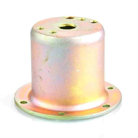
- The flange. A formed head at one end. It spreads the load – this is what stops a rivet from tearing through the sheet it is holding. Its thickness, diameter and bearing surface are the load-carrying design.
- The rim or tail. The other end. Where it is a rivet, this is what deforms during installation. Where it is a grommet, this is what the cable or tube passes through and what clamps the material.
So the controlling dimensions follow directly: for a rivet, flange diameter and thickness; for a grommet, the rim’s inner diameter and its flange bearing area; for a bushing, the body’s OD and length. The tolerance on flange and rim dimensions at +/-0.05 mm is exactly where this process earns its cost, and it is why the wall is specified as “controlled by the draw” rather than to a tight number – the wall is not the feature anyone is buying.
Why these are drawn rather than machined or cold-formed
A rivet is a classical cold-heading product, and a turned bushing is a classical turning product. The drawn route wins in a specific set of circumstances, and understanding when they apply tells you whether a drawn fastener is the right choice for your design:
| Drawn is the right choice | Thin-wall tubular bodies; parts with a flange that must be formed integral to the tube; high volume where the material efficiency of a blank-based process matters; parts where the wall needs to be a controlled, uniform value rather than the variable wall of a turned part; and any part that must be formed from strip in a continuous, automatable operation. |
|---|---|
| Heading or forging is better | Where the head must be thick, hardened, or of a controlled hardness – a structural rivet’s head is often much stronger than its shank, which a drawn part cannot achieve because drawing work-hardens uniformly. |
| Turning is better | Where you need a thick-wall part, a controlled bore with a fine surface, a thread, or a feature with high stiffness in a short length – all of which a thin-wall drawn part cannot provide. |
| A separate insert is better | Where the fastener must be in a different material from the flange – a steel rivet with a brass grommet, for example – or where it must be replaceable without removing the panel. |
The honest engineering point: if the part needs a thick head, a hardened head, or a thick-wall body, a drawn part is the wrong process and the drawing review should say so rather than quote it.
Installation, and the property the design must have
On an installed fastener, the design requirement is usually stated as a strength value – a tensile strength, a shear load, or a clamp force – and each implies a different design constraint:
- Pull-out (tensile). The flange must be large enough that the bearing stress on the joined sheet does not tear or yield the hole. This is a stress-area calculation: a bigger flange spreads the same load over more material. On a soft sheet material, the sheet tears before the rivet fails, and the only fix is a bigger flange or a washer.
- Shear. The shank’s cross-section carries it. This is where a drawn part’s uniform, controlled wall is an advantage – and where a part with an inconsistent wall will fail at the thin point rather than predictably.
- Clamp (bearing). The flange’s bearing area under a head carries it. Here the flange’s flatness matters, because a crowned or dished flange contacts only at its edges and the load goes through a much smaller area than intended.
- Fatigue. A joint that is cyclically loaded – a vibration application – fails at the joint, and the failure location is usually the edge of the hole in the joined sheet, not the fastener itself. A larger hole and a larger flange both improve fatigue life, which is counterintuitive and well established.
And the installation process itself sets requirements. For a rivet, hole diameter and rivet diameter have to be related correctly – a hole that is too small will expand the rivet and may work, a hole that is too large will not set it properly, and the correct relationship is a specified one. For a press-fit bushing, the interference is a specified value, not a nominal fit.
Wall control and what “controlled by the draw” means
The specification says the wall is controlled by the draw rather than held to a stated tolerance, and this needs explaining because it is a real design decision rather than a gap. In a drawn part:
- The wall is set by the material thickness and the draw ratio. Thinner walls result from more aggressive draws and are harder to hold consistently.
- Interstage annealing is what keeps it even. Annealing between draws restores ductility so each stage thins the wall predictably rather than progressively. Without it, a part needing several draws would thin unevenly and the later stages would crack.
- The wall is measured by the draw, not cut. It is a consequence of the geometry and the material, so specifying it as a tight tolerance means specifying material thickness tightly – which is a purchasing requirement rather than a machining one.
Where the wall genuinely matters – a pressure boundary, a bushing’s load capacity, a heat path – it should be specified, and the specification should recognise that its accuracy comes from the incoming coil rather than from the press.
Finishes on a small fastener, and where they bite
Zinc, nickel or chrome plating, anodising, passivation or e-coat, with alternatives quoted alongside and samples approved in writing. On this part family, the finish decisions are unusually consequential because the part is small and the features are close together:
- The rim’s inner diameter shrinks with plating. On a grommet or eyelet the rim’s bore is the installation feature and it must be specified before or after plating. This is the single most common plating-related complaint on this part type.
- Thickness adds to the flange’s bearing area, which changes how it sits – usually for the better, since the flange is meant to spread load.
- Hydrogen embrittlement on a cold-worked steel part. A drawn part is work-hardened, and a high-strength steel fastener with a hard electroplate can be susceptible. Where a load-critical fastener is plated, this needs a stated bake or a plating process that controls it. This is a genuine failure mode and it is worth raising at review.
- Galvanising a small part. Hot-dip galvanising on small fasteners produces a thick, variable coating and is usually unsuitable. Zinc flake or electroplating is generally the right route.
- Anodising is for aluminium and brass parts, and it requires masking on any bore or mating surface – on a small part the masking operation can cost more than the anodising.
Carbon steel for structure, free-machining grade where a fastener needs it
Stock covers carbon steel in SPCC and DC01 grades, 304 and 316 stainless steel, aluminium and brass, with material substitutes proposed only with your written approval. The mapping for this family:
- Carbon steel for structural and general use. Cheap, stiff, and it needs coating. Free-machining grades are worth considering for volume where the part is machined as well as drawn.
- 304 and 316 stainless steel for corrosion resistance. Note that a drawn stainless steel part’s work-hardened condition is higher than 304’s mill condition, and it can raise galling at assembly – so on a stainless steel grommet or bushing the mating material is worth considering.
- Aluminium for lightweight or non-sparking applications – a real requirement in some industries – and for parts where a soft, forgiving installation is wanted. Aluminium grommets are common because they deform easily and will not damage a cable.
- Brass where conductivity, a non-magnetic requirement, or good corrosion resistance in specific media applies, and where the part needs a good bearing surface.
From a sample to a controlled drawing
Driven by your drawing or a physical sample. Where a sample is the source, four things must come out of the reverse measurement because they cannot be recovered from the physical part later:
- The material, stated with grade. A drawn part’s properties depend on its alloy and its anneal history, and these are not visible in a measurement.
- Wall thickness, as-measured. This is the number the part’s capacity is calculated from, and it should be recorded in the drawing’s notes rather than left implicit.
- Which dimensions are functional, and specifically whether flange and rim dimensions are measured before or after finish.
- The intended installation, including the hole diameter in the mating part and the load it carries. This is what lets the review check the joint rather than just the part.
Progressive and drawing dies are designed and built in house, so die cost stays transparent and the charge is refundable against agreed volumes. Free samples are available on standard items with reports attached. Pre-production samples come with a full inspection report, the part is proven before it is made in volume, and later batches are gauged back to the signed sample – which on a fastener is worth having, because a flange diameter that has drifted by 0.05 mm changes the bearing area and nobody would notice from the part alone.
Draw ratio, wall thinning, radii and trim — the design decisions behind a part like this are worked through with numbers in our deep drawn covers guide, and the Precision Deep Drawn Parts pages collect the rest of the family.
Specifications
| Item | Deep drawn fasteners |
|---|---|
| Brand | AUNOV |
| Designing | Driven by your drawing or a physical sample – samples are reverse-measured into a controlled drawing; the same drawing is used for every repeat order. |
| Tooling | Progressive and drawing dies are designed and built in house, so die cost stays transparent, and the charge is refundable against agreed volumes. |
| Samples | Free samples are available on standard items, with reports attached. |
| Materials | Stock covers carbon steel (SPCC / DC01), 304 / 316 stainless steel, aluminium and brass; material substitutes are proposed only with your written approval. |
| Surface finish | Zinc, nickel or chrome plating, anodising, passivation or e-coat; alternatives quoted with the quotation, samples approved in writing. |
| Processing | Progressive drawing through several stages, annealed between draws, then trim and pierce; first articles verify the whole flow before the run is released. |
| Equipment | Mechanical presses from 5 to 250 T and hydraulic presses 250-500 T, with in-line annealing furnaces, with CNC turning centres for secondary operations and CMM inspection. |
| Tolerance | +/-0.05 mm on flange and rim dimensions, wall controlled by the draw; dimensional reports accompany the first article. |
| Delivery terms | Shipping terms are set with the order: FOB, CIF or DDP, T/T or L/C, door delivery quoted. |
Frequently Asked Questions
Why are these fasteners drawn rather than machined or cold-formed?
Drawing gives a seamless wall and forms the flange, rim, and any step in the same hit, where machining would cut them from bar and cold-forming would need a separate operation for each. Past a few thousand pieces the drawn fastener is the cheaper and stronger part, with no seam to fail under load.
What load does the flange of a drawn fastener carry?
The flange carries the clamp load and the rim carries the flange, so both are sized together on the drawing rather than separately. The load path runs from the mating face through the rim into the wall, and that relationship is held in one setup so it repeats across the run.
Which steel is used for deep drawn fasteners?
Carbon steel for structure, with a free-machining grade where the fastener needs a thread or cross-hole cut after drawing. The grade is picked so the wall draws cleanly and any secondary machining does not weaken it, and certificates accompany the first article.
What is the minimum order quantity for drawn fasteners?
Runs start at 1,000 pieces, with tooling made in-house to your print. We return a quote within 24 hours of the drawing, and first articles are measured on the CMM before the full run so the flange and wall are confirmed on metal.
Related Products


Request a Quote for This Part
Send a drawing or sketch — get material advice, tooling cost and a per-piece price within 24 hours (working days).