
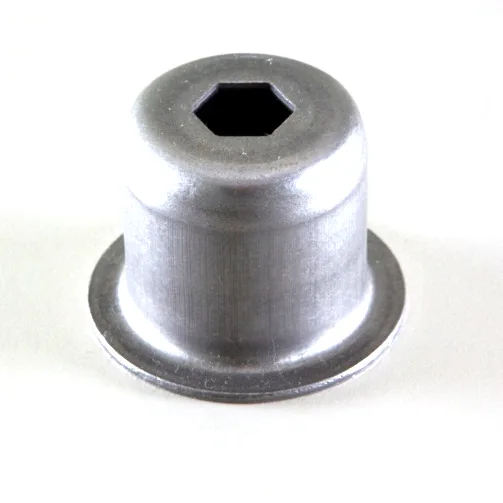
A dome cover is a pressure structure disguised as a lid, and its geometry is a free variable
A stainless steel dome plate cover is a shallow spherical or toroidal cap. That geometry is worth understanding properly, because on a dome the shape is not a styling choice – it is a structural decision with a measurable efficiency, and the same dome can be efficient or badly overstressed depending on how it is proportioned. A dome’s whole reason for existing is that a shallow curved shell is far stronger than a flat plate of the same weight, and the design has to exploit that rather than merely adopt the shape.
We multi-stage draw with interstage annealing, then trim and pierce in following dies, and every stage is logged against your part number, on 5-250 T mechanical presses and 250-500 T hydraulic presses and annealing furnaces in line, backed by CNC turning centres and a climate-controlled inspection room. Formed features to +/-0.05 mm with capability data on critical dimensions, and critical dimensions carry CMM data with the shipment. Stock covers carbon steel in SPCC and DC01 grades, 304 and 316 stainless steel, aluminium and brass, with material substitutes proposed only with your written approval. Plating, coating or polishing to suit the drawing, with the finish inspected alongside the dimensional report on the first article. This page is about dome proportions, the things that make one efficient and another wasteful, and the four dimensions that a dome drawing must state.
Proportion is the whole engineering of a dome
A dome’s structural efficiency depends on one ratio – the height-to-span ratio, often called the rise-to-diameter ratio. It determines what happens when the dome is loaded, and the behaviour changes completely across a fairly narrow range:
- A shallow dome, roughly up to about a tenth of its span in height, works mainly in membrane action. The material is in tension across the dome, and a shallow shell is enormously efficient – it can carry a substantial load at a fraction of the weight of a flat plate. This is the region where domes excel.
- A deeper dome, approaching a hemisphere, works partly in bending. Membrane action reduces and bending action takes over, and the efficiency drops sharply. A hemispherical dome is close to the worst of the possible shapes from a structural point of view, even though it is the most common shape people picture.
- A deep dished or ogival dome, between a shallow cap and a hemisphere, is the compromise, and it is usually where a cover that has to resist internal pressure ends up.
So the first thing a dome drawing should state is the rise-to-span ratio, or at least the height and the span as dimensions. Without those, “dome” is a shape rather than a specification, and a reviewer’s comment on the proportions cannot be made. This is the single most useful thing a customer can add to this drawing.
Thinning, and why a dome’s base is the problem
A dome is drawn, and the draw does something specific to it: the material at the dome’s shoulder – where the flat flange transitions into the curved section – is stretched in two directions and thinned more than anywhere else. Four consequences:
- The shoulder is the thinnest point on the part, and it is also where the stress is highest. A dome’s efficiency calculation is done at the thinnest point, so the nominal wall on the drawing is not the design value.
- A tight shoulder radius is a crack risk, because that is where the two directions of stretching meet. A generous radius there is a manufacturing requirement and it costs almost nothing.
- Multi-stage drawing with interstage annealing is what makes a dome possible. A deep dome in one draw would exceed the material’s forming limit, and the anneal between stages restores the ductility. Where a dome is deep, the anneal is not an optimisation – it is what makes the part achievable.
- Thinning varies the dome’s stiffness. Where the dome’s depth is controlled, the depth is set at the shoulder after the forming has happened, so the shoulder region determines the dome’s final shape as well as its strength. This is a real coupling between the geometry and the process.
Formed features at +/-0.05 mm, and which ones a dome can actually hold
Formed features to +/-0.05 mm is the stated band, and on a dome cover the features divide into two groups that behave completely differently:
- Features on the flange – the rim, mounting holes, a locating tab – are formed on a flat region and they are the ones that can be held to a tight band. These take the stated band and it is realistic.
- Features on the dome itself – a hole in the dome, a boss on the dome, a vent – are formed on a curved, work-hardened surface and they are much harder. A hole in a dome is not simply a pierced hole: the surface is curved, the punch has to work against a radius, and the hole’s position relative to the dome’s surface is a three-dimensional relationship. Where a tight tolerance is needed on a dome feature, it should be machined, and the drawing should say so.
The third category is the dome’s own dimensions – its height, its radius, and its roundness. A drawn dome’s height is affected by springback, and its shape is a consequence of the tool plus the material’s condition. On a dome where the height is functional – where it sets how far a dome protrudes, or how much clearance it gives, or the volume it contains – the height’s tolerance should be established from capability data rather than assumed, and the process should be capable of holding it.
Sealing, and the dome’s rim is where the leak happens
Where a dome cover seals against something, the seal is at the rim, and the rim’s requirements are the same as on any enclosure plus three that a dome makes worse:
- Flatness of the flange, against a named surface. A dome’s flange tends to be less flat than a flat-drawn pan’s because the forming of the dome leaves stresses in the flange, and a domed part’s flange is a stress-relief problem as well as a forming one.
- The flange’s warping over time, as the dome’s residual stress relaxes. A dome cover that measures flat at the first article can dish slightly over a season in a different thermal cycle, and a dished flange leaks. This is a real long-term failure mode and it is a reason to specify a realistic flatness rather than an aspirational one.
- Concentricity of the flange to the dome’s apex, where the cover has to register concentrically. This is a three-dimensional relationship between the flange and the dome’s formed axis, and on a dome it is more sensitive to the process than on a flat part.
Material, and the corrosion duty on a cover
Stock covers carbon steel in SPCC and DC01 grades, 304 and 316 stainless steel, aluminium and brass, with material substitutes proposed only with your written approval. On a dome cover:
- 304 stainless steel is the standard for a general cover, and it takes a fine surface, which matters where the cover is visible.
- 316 stainless steel for salt, marine, and chloride-bearing environments, and for a cover in a process area.
- Carbon steel with plating where the cover is a structural or a shielding cover and cost governs, and it needs coating on both faces – the inside being the one nobody sees and where corrosion will start.
- Aluminium where mass matters, and it forms a dome well. The penalty is that a thin aluminium dome is less stiff, so a shallow dome’s efficiency advantage is reduced.
- Brass where a warm appearance or a specific corrosion behaviour applies, and it takes the best polish of the group – which is worth considering on a visible cover.
On a dome, coverage at the shoulder is worse than at the crown
Plating, coating or polishing to suit the drawing, with the finish inspected alongside the dimensional report on the first article. Four points on a dome:
- Coverage on the dome’s crown is better than at the shoulder, and the shoulder – the transition to the flange – is where coverage is hardest and where the coating thins. On a dome this is the same crevice problem as on any formed geometry, and it is where corrosion will start in a severe environment.
- A coating on the rim changes the seal. On a cover that seals, the rim should be masked or the coating’s effect on the seal stated – a compressible film on a sealing rim creeps and a hard film under a gasket changes the compression.
- Coating thickness against the flange’s flatness. A coating on a flange that has already dished slightly can make it worse, because the film follows the surface and adds its own build. This is worth checking on a part whose flatness is marginal.
- Polishing on a visible dome. A polished dome shows the draw lines and any waviness more clearly than a matte finish does, because a specular surface reflects the form. On a visible dome this is worth stating – and if a matte or brushed finish is acceptable, it is more forgiving.
A dome is structural, or it is a shape
Eight things, and the first is the one that turns a shape into a specification:
- Height and span, and therefore the rise-to-span ratio, as dimensions rather than as a profile. This is what makes the dome structurally reviewable.
- Which features are on the flange and which are on the dome, because they can hold completely different tolerances and only the flange features can hold a tight band reliably.
- Wall thickness, with its minimum location, – the shoulder, and specifically the shoulder, not the crown.
- Shoulder radius, as a stated minimum, because that is where the draw is hardest and where cracking starts.
- Dome height tolerance, where the height is functional, established from capability data rather than assumed.
- Flange flatness, concentricity, and how they are measured, against a named surface and a stated support condition.
- Material grade and temper, confirmed in writing, since a dome’s final shape depends on the material’s condition and springback.
- Which surfaces are masked, and whether dimensions apply before or after finish.
Is this dome structural, or just a shape?
Is this dome structural, or is it a shape? If the dome has to resist an internal pressure – a sealed cover over a pressurised volume, a pressure vessel head, anything that is holding something in – then its proportions, its wall, and its material are a calculation and should be treated as one. If the dome is simply a cover with a rounded top for appearance or for a finger clearance, then the proportions are a style choice and the requirements are flatness, corrosion, and cost. These two readings produce completely different parts from the same word, and the difference between a shallow cap and a hemisphere is the difference between a highly efficient shell and a heavy one. Naming which of the two the part is, at enquiry, is the whole question.
If you are comparing this part with a machined or welded alternative, the guide to deep drawn covers lays out where drawing wins, where it loses, and what it costs either way.
Specifications
| Item | Drawn Cap with Hex Center Hole |
|---|---|
| Brand | AUNOV |
| Designing | Send drawings, or send a sample to be measured – a manufacturability review comes back with the quotation; the approved drawing is kept as the controlled master. |
| Tooling | Die design and toolmaking stay in house, so the die charge appears as its own quotation line, and the die remains dedicated to your part. |
| Samples | Samples are issued for approval before the run, so the part is proven before it is made in volume, and later batches are gauged back to the signed sample. |
| Materials | Stock covers carbon steel (SPCC / DC01), 304 / 316 stainless steel, aluminium and brass; material substitutes are proposed only with your written approval. |
| Surface finish | Plating, coating or polishing to suit the drawing; the finish is inspected with the dimensional report on the first article. |
| Processing | Multi-stage deep drawing with interstage annealing, trimmed and pierced in following dies; every stage is logged against your part number. |
| Equipment | 5-250 T mechanical presses, 250-500 T hydraulic presses and annealing furnaces in line, backed by CNC turning centres and a climate-controlled inspection room. |
| Tolerance | +/-0.05 mm on formed features, with capability data on critical dimensions; critical dimensions carry CMM data with the shipment. |
| Delivery terms | Delivery quoted per Incoterms 2020 – FOB, CIF or DDP – by sea or air, to your address. |
Frequently Asked Questions
How is the hex center hole located in a drawn cap?
The hex is formed or broached from the same datum as the drawn shell, so it stays centered and square to the cap face rather than wandering as a second setup. On a stainless steel cap we hold that relationship on the CMM because a hex that runs out from the bore will not seat the mating part.
Can a drawn cap be made without a draft angle?
A straight-wall cap needs a process that releases the part without a draft, which is why caps like this are drawn and then sized rather than simply pressed. The trade-off is tooling complexity, but it is what gives a vertical wall and a clean sealing face.
What seals the rim of a drawn cap with a hex hole?
The seal sits on the rim or a formed land, and the cap is drawn so that land is uniform all the way round – a wavy or thinned edge is where a dome or cap leaks. The rim is held to a tight band because, on a cover, the leak always starts at the edge.
Which material is used for a drawn cap with a hex center hole?
Stainless steel is typical for corrosion duty, with 304 or 316 chosen for the environment; brass or aluminium are used where weight or a specific finish decides. The material follows the service condition, and mill certificates accompany the first article either way.
Related Products


Request a Quote for This Part
Send a drawing or sketch — get material advice, tooling cost and a per-piece price within 24 hours (working days).