
A bushing is a bearing surface first, and the inside diameter decides everything
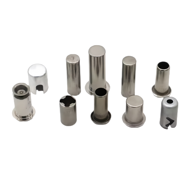
A deep drawn tube bushing looks like a simple sleeve, but the part earns its place in an assembly only through the surface it presents to a shaft, a pin or a bearing. We treat the inside diameter as the functional feature and the outside diameter as the locating feature, and we keep those two jobs separate on the drawing. A bushing that is held to a tight OD but left loose on the ID will locate perfectly and still rattle; one held tight on the ID but loose on the OD will spin in its bore. The engineering decision is which face carries the tolerance, and on a drawn bushing the answer is almost always the ID, because that is the surface the assembly actually touches.
We draw the shell on our own tooling, piercing the side holes in the same or a following operation and then machining the bore where it has to be precise. The as-drawn envelope is held to roughly +/-0.1 mm; the bore that meets the shaft is brought back to +/-0.03 mm by turning. Stating the whole sleeve to a machining tolerance costs money without buying function, so we quote which surfaces need which class and we log that decision against your part number. A reorder starts from recorded settings, not from a retune.
The side holes are what turn a plain sleeve into a function
The “with holes” in the name is the reason this part is not a commodity tube. Those holes are rarely decorative: on the bushings we make they are lubrication ports, vent paths, mounting detents or alignment keys, and each one changes the draw differently. A lubrication hole pierced through a thin-wall sleeve must be placed where the wall is still supported, because piercing removes material that the next forming station would otherwise rely on. A vent hole near a blind end relieves trapped air during assembly but becomes a leak path if it breaches a seal land.
- Lubrication ports are pierced before any final sizing so the burr is pushed inward and can be tumbled or honed away rather than left standing proud into the bore.
- Mounting detents are held to +/-0.05 mm on position because their only job is to register against a mating feature; a sloppy position defeats the bushing.
- Alignment keys cut through the wall need the slot width controlled, not just the hole diameter, and that is a piercing-and-trim operation rather than a simple punch.
- Vent paths are deliberately placed away from the seal land so the hole never becomes the route a fluid takes past the bushing.
Every hole we pierce is checked for burr height on the first article, because on a sleeve this thin a burr that points into the bore is a scratch on the shaft the first time it turns.
Drawing the envelope, then turning the bore, is the cheapest way to be precise
A drawn tube is cheap at length because each part is a press cycle, but drawing alone cannot hold a bearing bore. The split we use is deliberate: the drawing buys the outside shape, the wall and the overall length; the turning buys the inside diameter and any face that must seat something. The two operations are planned together so the drawn wall is thick enough to leave material for the bore without breaking through.
On stainless steel in the 0.5 to 2.0 mm wall range we draw in staged reductions rather than a single aggressive hit, annealing between stages where the wall work-hardens. After drawing we chuck the shell and bore it on CNC turning centres, holding the ID to +/-0.03 mm and the bore finish to a level that suits the bearing or bushing that runs inside it. We measure the bore with the same climate-controlled CMM that sees the first article, and the concentricity between OD and ID is reported as a single runout number rather than two separate diameters.
Concentricity is the measurement that actually matters on a sleeve
Wall thickness variation is the silent failure mode of a drawn bushing. A sleeve can have a perfect OD and a perfect ID on paper and still have a thin spot that dents under a press fit, because the two diameters were not held true to each other. We measure concentricity as total indicator reading between the finished OD and the finished ID, and we accept it against a limit that protects the thinnest wall section, not against a nominal centre.
- Why it shows up as vibration. An off-centre bore puts the rotating mass out of balance at speed, and on a bushing that carries a shaft the symptom is noise and premature wear rather than an obvious dimensional reject.
- Why we draw before we turn. Turning a centred bore into an off-centre shell simply moves the thin wall to a different clock position; the only way to control it is to hold the drawn shell round and then bore from that same datum.
- What the limit is. On these bushings we hold the ID-to-OD runout to a fraction of the wall thickness, and we record it per batch so a later order can be compared to the first rather than to a generic standard.
304 or 316L on a bushing, and the chloride question at the seat
For a stainless steel bushing the grade choice is not cosmetic. 304 draws cleanly, machines well and covers the vast majority of indoor and lightly exposed duties. 316L is the answer where chlorides are present: coastal air, washdown, road salt, process fluids. The difference is the molybdenum in 316L, and it matters specifically at the bearing seat, because that is where a crevice forms and a passive film gets broken and has to reform.
We do not upgrade every bushing to 316L by default, because 316L is more expensive and slightly less formable, and on a dry indoor assembly it buys nothing. We do upgrade without argument where the bushing will sit in a wet or chemical environment, and we note the grade on the first-article documentation so the material certificate and the part agree. Whichever grade is drawn, we passivate after machining so the turned bore carries a fresh, uniform passive layer rather than the disturbed one left by the cutting tool.
The cost tradeoff on a bushing is almost always between wall thickness and machining. A thicker drawn wall costs little at the press but leaves more to remove at the lathe; a thinner wall is cheaper to machine but risks the thin-spot failure described above and limits how much the bore can be cleaned up. We pick the wall from the assembly’s press-fit requirement first, then set the bore stock to the minimum that still guarantees a clean cut, and we keep that combination fixed once a first article is approved. Changing the wall on a later order without telling us is the most common way a bushing that worked once suddenly scrapes at the press fit, because the bore cleanup that used to hide the variation is no longer there.
How we verify a stainless steel bushing before it leaves the floor
Acceptance on a drawn bushing is not a single gauge pass; it is a short list of measurements tied to the features that fail. Our verification routine for this family runs in order:
- Mill certificate per heat, checked against the grade written on the drawing before any part is cut.
- First-article CMM report covering OD, ID, length, hole positions and the OD-to-ID runout, signed and shipped with the samples.
- Wall thickness at four clock positions on a sampled part, to confirm the thinnest section is above the limit that protects the press fit.
- Burr height on every pierced hole, inspected on the first article and then watched by per-batch sampling.
- Bore finish checked against the requirement the mating bearing or shaft needs, not against a generic number.
- Passivation confirmation on machined stainless steel, so the turned surface is corrosion-ready and not just cosmetically clean.
Each shipment carries the dimensional report and the material certificate under your part number, and the process settings that produced the batch are archived so the next order is a repeat rather than a redevelopment.
Draw ratio, wall thinning, radii and trim — the design decisions behind a part like this are worked through with numbers in our deep drawn covers guide, and the Precision Deep Drawn Parts pages collect the rest of the family.
Specifications
| Item | Stainless Steel Deep Drawn Tube Bushings with Holes |
|---|---|
| Brand | AUNOV |
| Designing | Send us your 2D drawing, or mail a sample for measurement, DFM feedback is returned with the quote. |
| Tooling | Dies designed and built in our own toolroom, held and maintained under your part number. |
| Samples | First-article samples ship with dimensional data and material certification. |
| Materials | 304 / 316 stainless steel is the primary stock for this part, alongside carbon steel (SPCC / DC01), aluminium, brass and copper, per the drawing. |
| Surface finish | Surface treatment per the drawing: plating, e-coat, powder coating, anodising, passivation, per your print. |
| Processing | Staged deep drawing, with in-line annealing where the draw ratio requires, with piercing and finish machining under the same roof. |
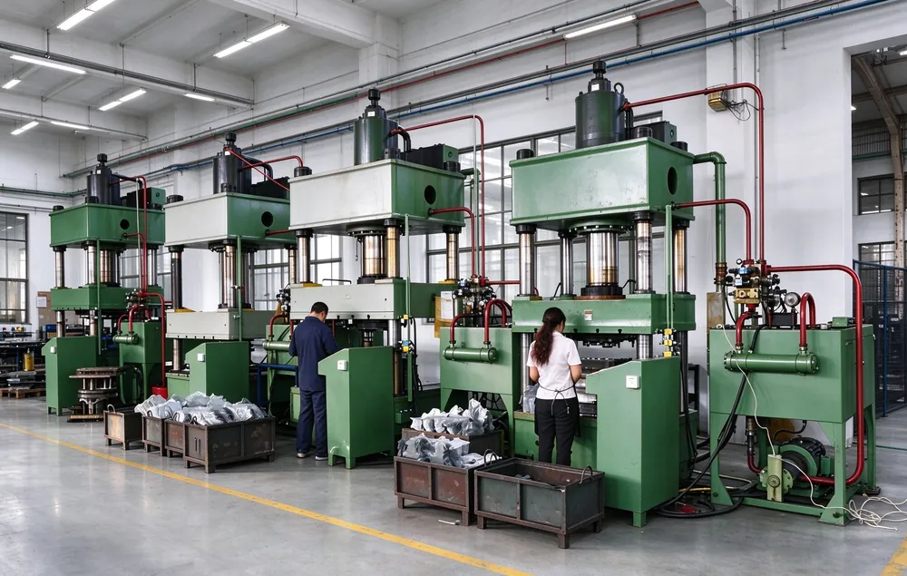
| Equipment | 5-250 T mechanical presses plus 250-500 T hydraulic presses, CNC turning centres, climate-controlled CMM room. |
| Tolerance | Drawn tolerances held to +/-0.1 mm, with machined features to +/-0.03 mm. |
| Delivery terms | Prices FOB, with DDP for EU and US on request, T/T and L/C accepted, D/P for established customers, call-off schedules supported. |
Frequently Asked Questions
Which surface carries the tolerance, the inside or the outside diameter?
Almost always the inside diameter, because that is the surface the assembly actually touches. A bushing held tight on the outside diameter but loose on the inside will locate perfectly and still rattle, while reversing the priorities gives a sleeve that spins in its bore.
Why draw the envelope and then turn the bore instead of machining the whole sleeve?
The drawn envelope is held to its own band and only the bore that meets the shaft is brought back by turning, which puts the fine tolerance exactly where function needs it. Stating the whole sleeve to a machining class costs money without buying function, so we quote which surfaces need which class and log that decision against the part number.
Why does concentricity matter more than wall thickness here?
Two diameters can sit comfortably within their individual limits while the wall between them is offset, and a sleeve like that loads its shaft unevenly and wears on one side. Concentricity is the measurement that actually describes whether the bore runs true to the locating surface, which is what the assembly sees.
When does choosing between 304 and 316L actually bite?
At the seat, and specifically where chlorides sit in the crevice between bushing and housing rather than in bulk exposure. That is a crevice question rather than a general corrosion question, so the grade should be decided against what collects at the seat in service, not against the ambient environment alone.
Related Products
Request a Quote for This Part
Send a drawing or sketch — get material advice, tooling cost and a per-piece price within 24 hours (working days).