
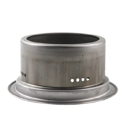
Punching parts: the question is what gets pierced and when
“Deep drawn punching parts” names a family rather than a single part, and the ambiguity is worth resolving before anything else, because in this shop the word punching covers two quite different operations. A hole can be pierced – sheared out of a flat sheet by a punch and die, which is fast, cheap and accurate. Or it can be punched in the older sense of being formed in a shaped die with a shaped tool, which forms a feature rather than removing material. Which one a part needs decides almost everything about how it is made, and the cost difference between the two is large.
We draw from coil or blank with interstage annealing so walls thin evenly, and in-process checks sit between stages rather than only at the end. Presses run 5-250 T mechanical plus 250-500 T hydraulic with in-line annealing; secondary operations run on CNC turning centres and inspection is on the CMM. General tolerance on drawn sections is +/-0.1 mm with +/-0.03 mm on machined seats. This page covers the decisions that turn an ambiguous description into a manufacturable part.
Pierce or form: the first fork in the road
Most features in a deep drawn part fall into one of four categories, and each has a different cost and a different accuracy:
| Pierced hole | Material removed by a punch entering a die. Fast, repeatable, accurate in the flat, and the burr side is predictable. The default for any opening in a flat region. |
|---|---|
| Drawn hole | Material is pushed through a die without a punch – the hole forms by plastic flow. Used where the hole must be in a formed wall and the drawing has to continue around it. Slower, and the wall around the hole thins. |
| Formed feature | A boss, a rib, a lanced tab, a dimple – material is displaced but not removed. Cheap in a progressive die, and the feature can double as a locating or stiffening element. |
| Secondary machined feature | Drilled, tapped, reamed or turned after drawing. The most accurate and the most expensive, and it is the right answer for a thread or a precision seat. |
When a customer sends a drawing that shows a tapped hole in a 1.5 mm drawn wall with no boss, the review has to raise it, because a tap in thin sheet does not have enough thread engagement to survive being tightened. The options, in order of preference: draw a boss to give the tap something to bite into, insert a pressed-in nut, or accept a clinch nut as a deliberate assembly choice. All three are reasonable; none of them is what a 1.5 mm tapped hole is.
Pierce before you form
The single most useful rule in a deep drawn part with holes: every hole that can be pierced in the flat should be. A hole pierced in a flat blank is located in two dimensions by a rigid tool, so its position is essentially a feed-and-pilot problem. The same hole pierced after the part is formed sits on a curved, work-hardened surface and inherits all the forming variation underneath it.
Where a hole must be in a formed wall, the design measures that reduce the penalty are:
- A flat pad or a drawn flat. Form a local flat around the hole, pierce there, then form the surrounding geometry. This is common for a side hole in a drawn boss.
- Keep it clear of the forming radius. A hole near the punch nose radius is in the highest-strain, least-stable region of the part, and its position will move as the wall thins.
- Make it the same cut as the outline. A hole that is trimmed out in the same operation as the outline gets located by the same die, and no additional piercing station or its own position error.
Material utilisation: where the money actually is
On a small drawn part, material is often the largest single cost in the piece price, and material utilisation is a design decision rather than a production accident. The levers, in rough order of value:
- Blank diameter. A blank that is 2% too large costs 4% of the material in every part. The relationship between blank size and cup diameter is fixed by the draw ratio, so the only way to reduce it is to change the geometry – a smaller blank for the same part means a different shape or a two-part assembly.
- Nesting and strip layout. Progressive die parts are nested along the strip, and the layout is a genuine optimisation problem. A part with an odd profile can nest well; a part that is roughly square and roughly the strip width nests badly. Whether a part is a good progressive-die part is a question worth asking early.
- Offcut recovery. The skeleton from piercing and the blanking web are real material, and we account for them. On small brass and steel parts the recovery is meaningful.
- Material thickness choice. The most direct lever of all, and the one that must be tested against function. Thinner material is cheaper per part and lighter, but it draws less well, forms less rigidly, and pierces with more burr.
Grade and temper are confirmed in writing before tooling for exactly this reason. A material that has been substituted to hit a price is the most common cause of a drawing that suddenly has a burst at the punch nose.
Burr, edge condition and the downstream cost
A pierced hole leaves a burr, and a sheared edge has a work-hardened zone and a heat-affected tint near it. On a part that goes into a visible assembly or that seats against a gasket, the burr side has to be specified. On a part that carries a cyclic load, the edge condition matters for fatigue – a sheared edge is a better fatigue initiator than a ground edge, and a burr is worse than both.
Three edge treatments, and what each is for:
- Deburring. Removes the loose burr and leaves the work-hardened layer. The normal requirement, and specified as a burr height rather than as the word deburred.
- Deburring plus polishing or vibratory finishing. Further work-hardens and stress-relieves the surface, improving fatigue life and appearance. Worth it where the part is cyclically loaded.
- Grinding or a machined edge. Only where an edge is a sealing surface or a bearing surface, and the cost is a separate operation.
For any part in contact with a finger, a valve, or food or medical fluid, edge condition stops being cosmetic and becomes a specification with a measurable limit.
Threaded and machined features in a drawn part
Where a drawn part carries threads or a precision seat, the secondary operations take over from the drawing for those features. We run CNC turning centres for this, and it is worth being clear about the consequences for the drawing and the schedule:
- Threads. Tapped in the drawn wall or cut on a turned boss. A tap in a drawn hole needs the hole to be undersize for the tap and to be concentric enough that the thread does not run out. A boss turned as a secondary op is more reliable and usually more economical at volume.
- Seats. The +/-0.03 mm band on machined seats exists because a drawn face cannot hold that. The stamping must leave enough material for the cut – specify the machining allowance on the drawing.
- Concentricity. A secondary operation introduces its own datum. The drawing should say what the machining is located from, because otherwise the machining will locate from whatever is easiest on the machine.
Ordering matters as much as tolerance. A secondary operation that adds heat or clamping force can distort a thin drawn part, and a part machined while still attached to a spring or carrier is a different proposition from one machined loose. Where distortion is a risk, the route is designed so the machining happens at a controlled stage.
Finishing, and getting a quotation that means something
Surface treatment is natural, plated or coated per the print, with masking and laser marking available where needed, and the agreed finish is logged. On a small drawn part the finish can be a significant share of the piece price, so it belongs on the drawing rather than in a conversation. The questions worth resolving: is any face masked, is the finish required inside a cavity or only outside, and is the part dimensionally critical after plating or before it.
The quotation follows your print, not a catalogue. Unusual walls, threads or tolerances are checked for feasibility first, and finer tolerance bands are confirmed from capability data before quoting rather than discovered at first article. Progressive and drawing dies are designed and built in house, so no tooling step is outsourced, and first-article timing is measured from the tooling start date.
If you are starting from a sample rather than a drawing, the most useful thing you can send is the sample plus a note of what the holes are for. Whether a feature is a piercing or a forming decision, whether a hole carries a fastener or a fluid, and whether the part has to be leak-tight are the three facts that let a manufacturability review give you a specific answer instead of a cautious one.
Draw ratio, wall thinning, radii and trim — the design decisions behind a part like this are worked through with numbers in our deep drawn covers guide, and the Precision Deep Drawn Parts pages collect the rest of the family.
Specifications
| Item | Deep drawn punching parts |
|---|---|
| Brand | AUNOV |
| Designing | The quotation follows your print, not a catalogue – unusual walls, threads or tolerances are checked for feasibility first. |
| Tooling | Progressive and drawing dies are designed and built in house, so no tooling step is outsourced, and first-article timing is measured from the tooling start date. |
| Samples | Sample lead time is quoted with the order, and the approved sample governs the run. |
| Materials | Standard stock: carbon steel (SPCC / DC01), 304 / 316 stainless steel, aluminium, brass; grade and temper are confirmed in writing before tooling. |
| Surface finish | Natural, plated or coated – the print decides, and the agreed finish is logged; masking and laser marking available where needed. |
| Processing | Deep drawing from coil or blank, with in-process annealing so walls thin evenly; in-process checks sit between stages, not only at the end. |
| Equipment | Mechanical presses 5-250 T plus 250-500 T hydraulics, with in-line annealing; secondary ops run on CNC turning centres, inspection on the CMM. |
| Tolerance | +/-0.1 mm general on drawn sections, +/-0.03 mm on machined seats; finer bands confirmed from capability data before quoting. |
| Delivery terms | FOB, CIF or DDP per Incoterms – payment by T/T or L/C, with shipping quoted door-to-door. |
Frequently Asked Questions
When should a feature be pierced, before or after forming?
It depends on whether the feature has to stay put while the wall moves. Features that must hold their position relative to formed geometry are pierced after forming, because a hole pierced into a blank migrates as material is drawn past it. A feature sitting in a genuinely flat region can be pierced first, but the decision belongs on the drawing rather than on the shop floor.
Where does the money actually go on a pierced drawn part?
Material utilisation is usually the largest single lever. How the blank nests, how much is left as skeleton and how many parts come off a coil decide more of the piece price than the pierce count does, so the two are reviewed together rather than separately.
Why is burr and edge condition worth specifying?
Because the cost of burr is paid downstream, in deburring, in sealing faces that leak, in assembly that hangs up and in hands that get cut. An edge condition written into the drawing costs nothing and prevents all four.
What tolerances apply, and what does a usable quotation need?
General tolerance on drawn sections is +/-0.1 mm with +/-0.03 mm on machined seats, and finer bands are confirmed against capability data rather than assumed. A quotation that means something also states which features are machined, which are as-drawn, and what the finish has to do.
Related Products



Request a Quote for This Part
Send a drawing or sketch — get material advice, tooling cost and a per-piece price within 24 hours (working days).