
CAPABILITY
Deep Drawing & Metal Stamping Capabilities
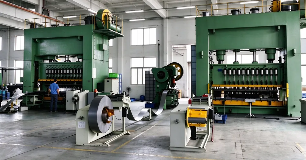
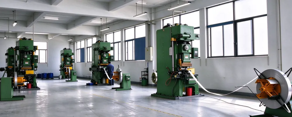
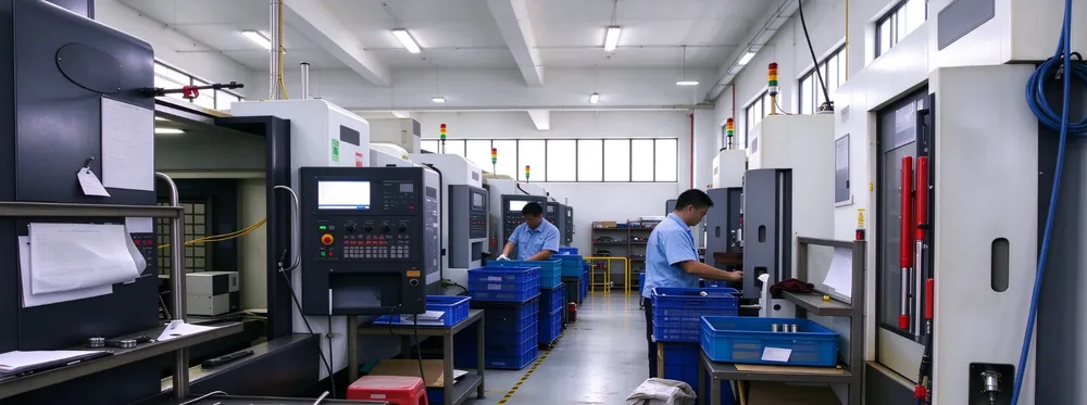
In-house tooling, 5–250T mechanical presses, 250–500T hydraulic presses, CNC finishing and full inspection — every step under one roof.
Everything Your Part Needs, In One Factory
A deep drawn or stamped part passes through six disciplines before it reaches your dock. Click any capability below to see the equipment, the engineering behind it and the tolerances we hold.
One Floor. One Team. No Hand-Offs.
One Factory, Every Step In-House
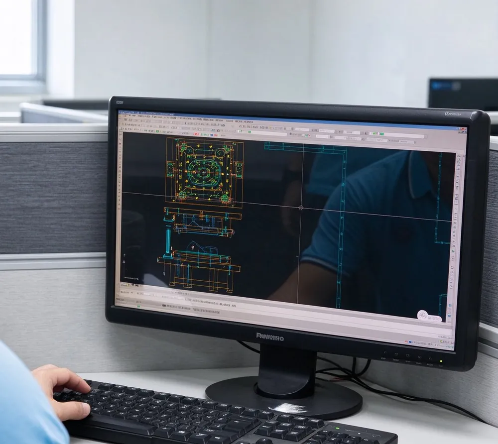
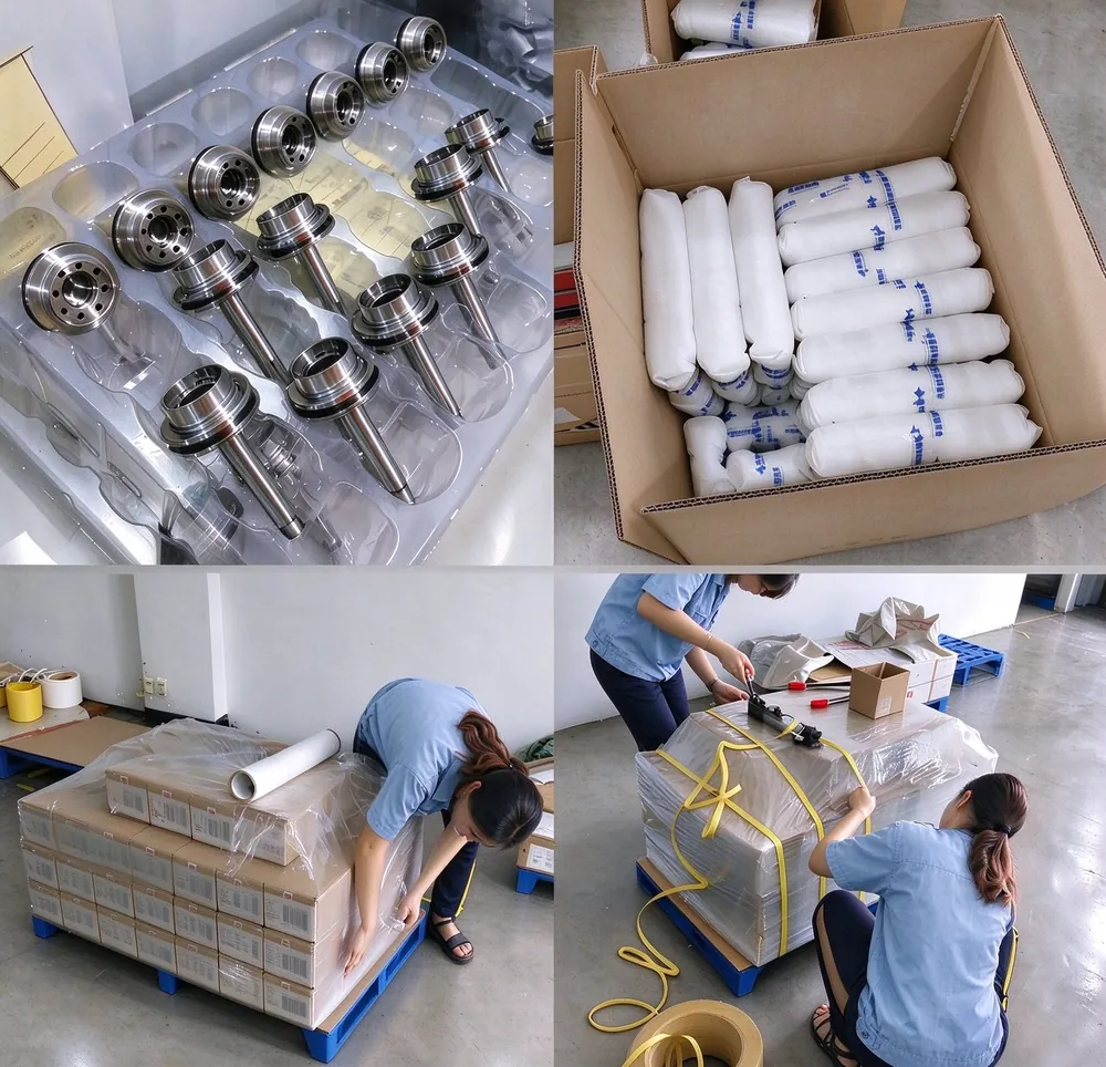
Press lines, CNC cells, tooling design, laser welding and packing all under one roof — so quality never leaves the building.
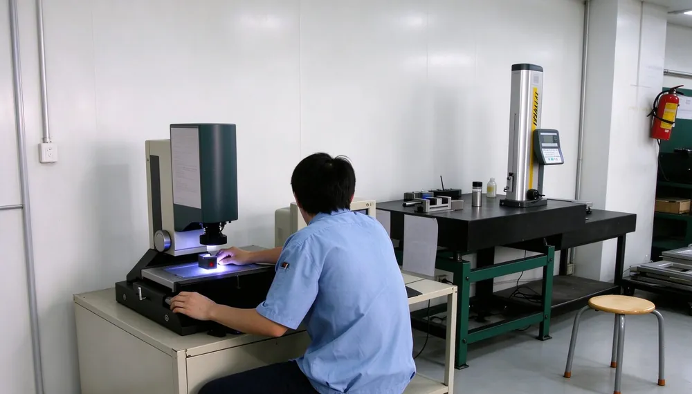
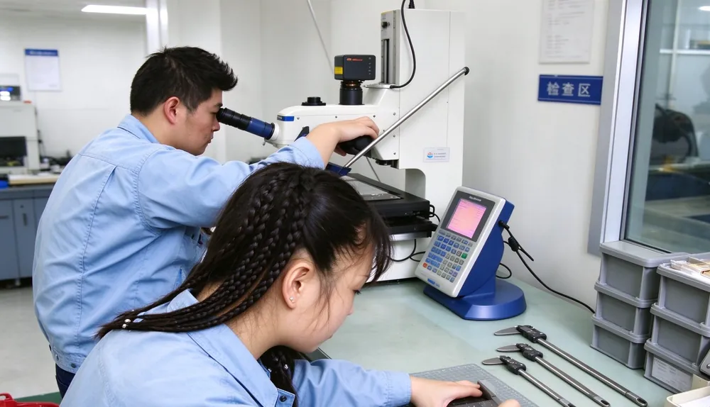
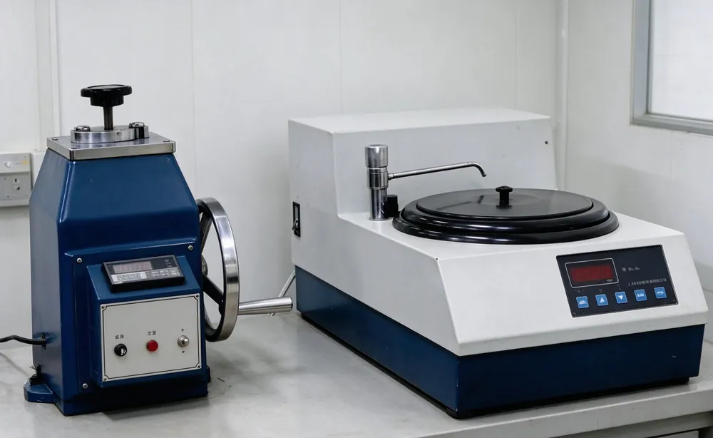
Inspected In-House, Before Every Shipment
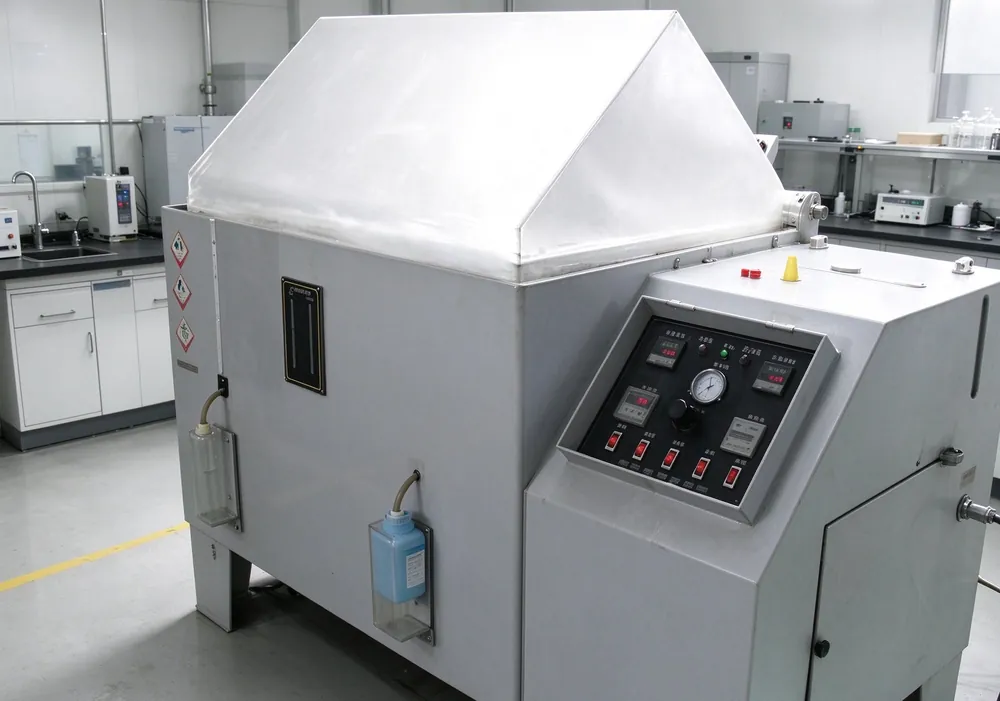
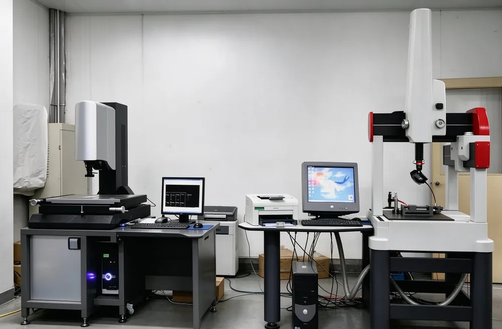
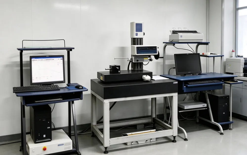
Dimensional checks on CMM and vision systems, material verification, metallography and salt-spray corrosion testing — all done on our own floor, never outsourced.
The Numbers That Define What We Can Draw
Capability claims are only useful if they are specific. The envelope below is what our presses, toolroom and inspection lab are set up to hold; anything outside it is a conversation rather than an automatic no. Where a drawing sits close to a limit, we say so at the DFM stage instead of at the first-article inspection.
| Parameter | Range | Note |
|---|---|---|
| Press capacity | 5–500 t | Mechanical and hydraulic lines, prototype runs through volume |
| Material thickness | 0.15–3.0 mm | Cold-rolled steel, stainless steel, aluminium, copper, brass |
| Single-pass draw depth | to 150 mm | Deeper shells by multi-stage drawing with intermediate anneal |
| Drawn diameter | to 300 mm | Beyond that, tonnage and blank control decide the route |
| Limiting draw ratio (LDR) | DC04 2.1–2.2 · 304 1.85–2.05 · 5052 1.80–1.95 | Set by the blank thickness-to-diameter ratio |
| Wall thickness tolerance | ±0.05 mm (±0.02 mm after ironing) | Ironing also lifts the surface finish |
| Ironing wall reduction | 20–35% steel · 30–50% aluminium, copper, brass | Per pass, against the incoming wall |
| Surface finish | Ra 1.6–3.2 µm as drawn; 0.1–0.8 µm electropolished | Measured on the finished part, not the tool |
| Minimum order | 1,000 pcs | Shorter runs quoted case by case |
How Each Grade Behaves on the Press
Material behaviour, not the shape, is usually what decides whether a shell draws in one hit or four. These are the families we stock and the behaviour to expect from each. Mill certificates to EN 10204 3.1 or 2.2 are verified on incoming coil, so the grade on the drawing is the grade in the part.
| Family | Grades we run | What it does in the die |
|---|---|---|
| Low-carbon steel | SPCC, DC01–DC06 | Good formability and the highest draw ratio; the default for shells and enclosures |
| Austenitic stainless steel | 304, 316L | Work-hardens fast, so it wants higher blankholder force and a controlled pass count |
| Ferritic stainless steel | 430 | Less work hardening than 304/316L and drawable, with lower corrosion resistance |
| Aluminium | EN AW-5052, 5754, 3003 | Draws well in O temper; 6xxx grades such as 6061-T6 do not deep draw and stay to shallow work |
| Copper and brass | C1100, C2600 | Excellent formability, chosen where conductivity or corrosion resistance leads |
The Settings That Decide a Clean Draw
These are the figures our toolroom and press floor actually work to, and they explain why a quotation looks the way it does. Corner radii and clearances are quoted as multiples of stock thickness, because that is how the tool is actually specified.
One number is worth stating on its own: a plain drawn wall thins 15–25% at the punch corner and thickens 5–10% at the flange. That is material flow, not a defect, and a drawing that does not allow for it will produce parts that measure correctly at the rim and fail at the wall.
What Goes Wrong, and What We Change
This is the part of a capability page that actually shows process competence. Every defect below has a known root cause and a known correction, and most of them are visible in the tool design before the first part is made.
| Defect | Root cause | Corrective action |
|---|---|---|
| Wrinkling, flange or wall | Blankholder force too low; clearance too large | Raise blankholder force, add draw beads, reduce clearance |
| Splitting or tearing | Blankholder force too high; corner radius too small; poor lubrication | Reduce force, enlarge radii, improve lubrication |
| Earing | Planar anisotropy in the strip | Select rolling direction, use O-temper stock, adjust blank orientation |
| Springback | High-strength or thick-gauge material | Over-bend compensation, add a sizing pass, apply ironing |
| Orange peel | Coarse grain size relative to thickness | Move to a finer-grained grade |
| Scoring or galling | High friction, poor tool surface | Improve lubricant, refine tool roughness, apply TiN or TiCN |
| Thickness variation | Uneven material flow | Re-balance the draw ratio, review blank shape and blankholder profile |
The Standards We Work To, and How We Prove It
General tolerances reference DIN 6930-2 or ISO 2768-m unless the drawing says otherwise; geometric tolerancing follows ISO 1101, surface texture ISO 1302, and material certification EN 10204 type 3.1 or 2.2. Automotive programmes run to PPAP, IMDS and IATF 16949, with Cpk at or above 1.33 on the characteristics you nominate as controlled.
Verification is planned per part rather than per batch habit. First-article inspection on a new tool runs on CMM and optical measurement and is documented before production release. Production batches follow an agreed sampling plan covering outside and inside diameter, height, wall thickness, concentricity, flange flatness and surface roughness. Where the drawing marks a critical wall zone, thickness is verified by ultrasonic gauging or by destructive cross-section rather than assumed.
Leak and pressure requirements are reported against your own specification, in the units you asked for — pressure-decay or helium results in mbar·l/s against your acceptance limit, not a generic pass line on our paperwork.
Have A Drawing? Let’s Put It On The Press
Send it to [email protected] — material advice, tooling plan and a per-piece price within 24 hours.
What press tonnage range does Aunov run?
Aunov runs 5–250T mechanical presses and 250–500T hydraulic presses, matched to the part geometry.
What tolerance can Aunov hold on deep drawn parts?
±0.05 mm as standard, and ±0.02 mm with an ironing step.
What is Aunov’s minimum order quantity?
From 1,000 pieces, depending on part size and complexity.
How quickly can Aunov quote a new part?
Within 24 hours for most drawings.