
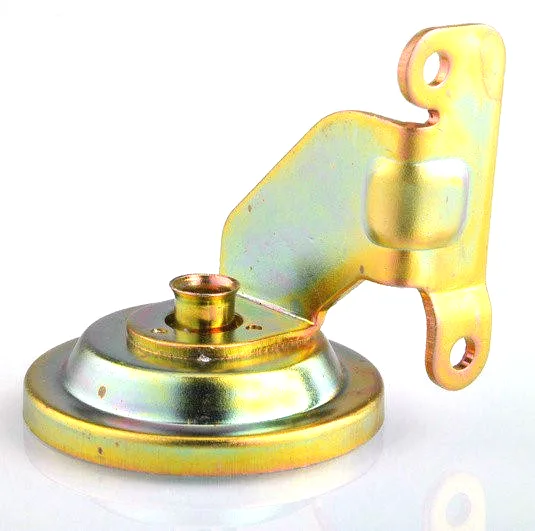
Forming a long coaxial shell, stage by stage
An electromagnetic switch housing is an awkward shape to form. It is a deep, narrow shell with a closed end that must be flat and concentric, a wall that must stay within a narrow band along a long length, and – because it carries magnetic flux – a grain structure that has to be restored after all that deformation. Getting from a flat blank to that shell is a sequence of draw stages, and the way the stages are planned decides whether the housing meets its dimensions, its magnetic behaviour and its cost. This page follows that sequence rather than the electrical function.
Draw ratio and why the stage count is fixed early
The first number that decides everything is the total draw ratio: the blank diameter divided by the finished shell diameter. A shallow housing might be made in one stage; a deep solenoid shell of the same diameter forces a chain of stages because a single stage can only reduce the diameter so far before the wall tears. Practical limits on our presses sit around 1.8-2.0 diameter reduction for the first draw of low-carbon steel and roughly 1.3-1.5 for each redraw, so a shell that needs a 3:1 overall reduction typically ends up as three or four draws. The stage plan then fixes the die set, the press tonnage, the number of operators and the total cycle time – which means the stage count is a commercial decision as much as a technical one, and it is set at the quotation, not discovered on the shop floor.
Wall thinning: the quiet dimension
Deep drawing does not thicken or thin the wall uniformly. The wall thins where the material is stretched over the punch nose and along the side wall, and it thickens slightly at the flange where the metal is compressed. On an ordinary can a little thinning is acceptable. On a switch housing it is not, for two reasons: the thin zone is a weak magnetic cross-section that saturates first, and it is also the zone most likely to crack in service at the crimp or the seat. We control the thinning by:
- Setting the die radii deliberately. A tight punch-nose radius thins the wall more; a generous one thins it less but needs a bigger stage. We tune the radius to the wall allowance, not to convenience.
- Choosing the blank and the lubrication per stage so the metal flows rather than stretches.
- Measuring wall thickness along the length on the first article and on periodic samples, so a drifting wall is caught before it becomes a saturation problem.
Where the print allows, we site the thinnest wall away from the bore and the seat, so the electrically and mechanically critical zones keep full section.
Annealing between stages, and what it does to the magnet
Every draw hardens the steel, and after a stage or two the material is too hard to form further and its permeability has fallen. Interstage annealing does two jobs at once: it softens the metal so the next draw is possible, and it recrystallises the grains so the magnetic properties come back. The schedule matters. An undersized anneal leaves the part hard and only partly recovered; an oversized one grows the grains and can make the steel brittle or change its magnetic character. We agree the anneal with the customer’s electrical requirement and, where the device is safety-related, we record the schedule against the part number so a repeat order is annealed identically. On a housing that carries flux, this is not a secondary heat-treat choice – it is a functional specification.
Coining the seating face
The end of the housing where the plunger seats has to be flat to control the residual air gap, and a normal draw leaves it slightly domed or wavy. Coining – squeezing the face between flat dies in a final station – flattens it and sets its height. The blank for that station has to be sized so the coin does not thin the face below the magnetic cross-section, and the coin force is set high enough to give a repeatable flat but not so high that it marks the outside. We verify the seat flatness and its height to the bore on the first article, because both are quick to measure and both directly predict how the switch will hold.
Springback at the open end, and the bore
The open end of a drawn shell springs back when it leaves the die, and on a housing whose bore must be round and concentric that springback is a real tolerance item. Two remedies are used: a sizing pass on the last stage that pushes the bore to a controlled diameter and removes most of the springback, and a slight over-draw that lets the elastic recovery land on the nominal. Where the print calls for a tight bore, we size it and check roundness with a bore gauge and the CMM rather than assuming the die alone holds it.
Blank development, gauge and lubrication
The blank is developed from the finished area plus an allowance for the flange to be trimmed and the metal drawn in, and the gauge is chosen from the magnetic cross-section with a forming allowance on top. Gauge is controlled at goods-in because a coil that is 5% thin draws well but saturates early. Lubricant is matched to the stage: a heavier film for the first deep draw where the strains are highest, a lighter one where the metal merely sizes. This is unglamorous work, but it is where the difference between a housing that passes its magnetic test on every batch and one that drifts sits.
Tooling, wear and the economics of the sequence
| Progressive die | All draw stages, the coin and the trim in one die, one press, high volume per stroke. Best when the annual volume is high and the stage count is modest. |
|---|---|
| Transfer line | Separate stations linked by a transfer, for very deep or large shells where a single progressive die would be too large or too highly loaded. |
| Individual dies | Used for low volume or for a first prototype run, when the tooling spend must stay small until the design is frozen. |
Long draws wear the die radius and the punch, and a worn radius changes the wall-thinning pattern. We track strokes against the part number and re-polish or replace the radius on a schedule, so the wall profile stays the same from the first batch to the tenth. For a housing that must anneal to a recorded schedule and hold a flat seat and a round bore, the tooling is not just a forming cost – it is the thing that keeps all three under control.
The same 18 to 70 mm envelope, drawn in three to five stages
- Diameter: 18-70 mm.
- Length: 20-110 mm.
- Wall: 0.8-2.5 mm.
- Stages: typically 3-5 draws with interstage anneal where required.
How many draws, from the draw ratio and our stage limit
How many draws will our housing need? It follows from the overall draw ratio and our stage limits, and we give you the stage count with the quotation.
Is the anneal mandatory? If the part carries flux and must pull in reliably, yes – the draw lowers permeability and the anneal restores it; we agree the schedule with your electrical requirement.
How do you keep the wall from thinning? By tuning the die radii, blank, lubrication and sizing per stage, and by measuring the wall along the length on the first article and on samples.
Will the seat be flat enough? We coin the seat in a final station and check its flatness and height to the bore on the first article; both numbers predict the hold force.
Specifying a formed electromagnetic switch housing
Give us the finished bore, length and wall, the magnetic duty and the steel grade you need, whether an interstage anneal is specified, the seat flatness and height, and the volumes and tooling budget. We answer with a stage plan, a wall-thinning allowance, a tooling route and a price – so the housing that comes off the press carries the flux and moves the plunger exactly the way the design intends.
Draw ratio, wall thinning, radii and trim — the design decisions behind a part like this are worked through with numbers in our deep drawn covers guide, and the Precision Deep Drawn Parts pages collect the rest of the family.
Specifications
| Item | Sheet Metal Forming Electromagnetic Switch Housing |
|---|---|
| Brand | AUNOV |
| Designing | Quotation follows the print, not a catalogue – a manufacturability review comes back with the quotation; revisions are re-quoted once rather than silently absorbed. |
| Tooling | Die design and toolmaking stay in house, so the die charge appears as its own quotation line, and ownership is confirmed on the quotation. |
| Samples | First-article samples ship with a dimensional report and material certificate, so any deviation is corrected at sample stage, and the signed sample is kept for future reorders. |
| Materials | Carbon steel (SPCC / DC01), 304 / 316 stainless steel, aluminium and brass are held on site; grade and temper are confirmed in writing before tooling. |
| Surface finish | Natural, plated or coated – the print decides, and the agreed finish is logged; the finish is inspected with the dimensional report on the first article. |
| Processing | Deep drawing on maintained presses, blank size and lubrication logged per run; first articles verify the whole flow before the run is released. |
| Equipment | Press shop running 5-250 T mechanical and 250-500 T hydraulic presses, annealing ovens on site, with CNC turning centres for secondary operations and CMM inspection. |
| Tolerance | +/-0.05 mm on flange and rim dimensions, wall controlled by the draw; capability is checked on the first article before the run continues. |
| Delivery terms | FOB Ningbo or Shanghai, T/T or L/C, with D/P accepted on repeat business; each volume tier carries its own quoted price. |
Frequently Asked Questions
How many draw stages does this housing need?
It follows from the total draw ratio set against what each stage can safely take. Practical limits sit around 1.8 to 2.0 diameter reduction for the first draw in low-carbon steel and roughly 1.3 to 1.5 for each redraw, so a shell needing about 3:1 overall reduction typically lands as three or four draws.
Why is the stage count fixed at quotation rather than on the shop floor?
Because the stage plan determines the die set, the press tonnage, the number of operators and the total cycle time. It is as much a commercial decision as a technical one, which is why it belongs in the quotation and not in a discovery made halfway through the job.
Why does this shell need annealing between stages?
For two reasons at once. Deformation damages the grain structure, and because the housing carries magnetic flux that grain has to be restored; the anneal is also what buys enough ductility for the next stage to take its reduction without tearing.
Which features are not left as drawn?
The seating face is coined rather than accepted from the draw, and springback at the open end and the bore is controlled deliberately. Both are planned as post-draw operations instead of being expected to come out of the forming stage.
Related Products


Request a Quote for This Part
Send a drawing or sketch — get material advice, tooling cost and a per-piece price within 24 hours (working days).