
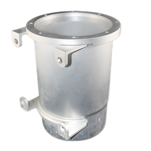
The Aluminum Deep Drawn Cylinder Shell with Mounting Ears is a straight drawn tube with two lugs pierced or formed out of the wall for bolting, and its tension is between a thin, straight bore and ears that want to distort that bore when they are made. The engineering below covers drawing the shell straight first and only then locating the ears so the bore stays round where it matters.
Drawing the shell straight before the ears are pierced
A cylinder shell is drawn in two or three stages depending on the length-to-diameter ratio. For a 100 mm outside-diameter, 150 mm long shell from 1.2 mm 6061, we blank at about 165 mm, draw to 110 mm in stage one, redraw to 100 mm in stage two, and iron the wall to 1.15 mm in stage three. The redraws are what keep the wall straight – a single deep draw on a 1.5:1 shell throws the wall into a taper that no ear location can correct later. We hold the shell straightness to 0.1 mm over the 150 mm before any ears are touched, because an ear located on a bowed shell points where it was drawn, not where the assembly wants it.
The base of the shell is closed or open per the drawing; for an open shell we trim the mouth and the tail square to +/-0.1 mm so the ears, when formed, reference a known axis. Straightness is measured on a CMM at first article and then checked with a V-block roll in production.
- 100 mm OD, 150 mm long, 1.2 mm 6061; three draw stages to hold the wall straight.
- Straightness 0.1 mm over length before ears are formed.
- Trim both ends square to +/-0.1 mm to reference the ear axis.
Between stages we anneal the 6061-T4 at 415 degrees for 40 minutes whenever the cumulative reduction passes 20 percent, because 6061 work-hardens fast and an unrelieved third stage cracks at the mouth. The stage reductions are planned as 40 percent, then 30 percent, then a 10 percent iron, which keeps each pass below the local necking limit while still landing the wall at 1.15 mm. We size the inter-stage clearance 0.05 mm over the previous outside diameter so the wall irons rather than re-thins at the corner.
Locating the mounting ears without distorting the bore
The ears are the shell’s only attachment, so their position drives the assembly, but making them is what threatens the bore. We form the ears by local stretch-forming two lugs out of the wall rather than welding separate brackets, because a weld on a thin drawn shell is a crack waiting to happen. The ears are located off the shell axis with a hard tool that backs up the bore with a mandrel, so the stretch does not pull the bore out of round at the ear root.
Ear position around the circumference is held to +/-0.1 mm and the ear centre line to the shell axis to 0.2 mm, measured on a CMM at first article. The two ears are located off a common centre so they stay opposite each other even as tooling wears; an ear that drifts throws the whole mount out of square.
- Stretch-form the ears from the wall on a mandrel-backed tool; never weld brackets to thin shell.
- Locate both ears off a common centre to stay opposite within wear drift.
- Hold ear position +/-0.1 mm; ear-to-axis 0.2 mm; CMM at first article.
Aluminium grade for a drawn cylinder with ears
6061 is the right call for an eared shell because the ears need strength in shear and 6061-T6 after forming carries it; 3003 would form the ears more easily but the lug would bend under bolt load. We draw 6061 in the T4 temper so it forms without cracking and then age it to T6 after the ears are made, so the lugs are fully hard where they are loaded. For a shell that only needs light ears we use 5052-H32, which forms the lugs without the T4-to-T6 step.
Finish is anodise at 12-15 microns, and we anodise after the ears are formed so the stretched lug material – thinnest at the ear root – is fully covered. A lug that anodises thin at the root is the one that corrodes and then tears.
- 6061-T4 drawn, aged to T6 after ear forming for lug strength.
- 5052-H32 where the ears carry light load and the T-step is unwanted.
- Anodise after ear forming; cover the thin ear root fully.
Holding bore roundness and ear position tolerance
The bore is the shell’s functional diameter – it carries a piston, a sleeve or a bearing – so it is held round within 0.03 mm TIR and to +/-0.03 mm on diameter, machined after drawing. The ears are allowed the looser +/-0.1 mm because they only locate the shell in its mount, not within it. We measure bore roundness on a CMM at first article and then air-gauge it in production, because a bore that goes 0.05 mm out of round at the ear root is the hidden cause of a piston that binds.
Ear hole position is held to +/-0.1 mm from the ear centre, because the bolt must pass without reaming the lug. The ear thickness at the root is mapped to 1.0 mm minimum – below that the lug tears under the bolt clamp, which is the failure we design out at the sample.
- Bore roundness 0.03 mm TIR, diameter +/-0.03 mm, machined after draw.
- Ear hole position +/-0.1 mm; ear root thickness 1.0 mm minimum.
- Air-gauge the bore every run; CMM the ear map on first article.
The bore is machined on a CNC turning centre after the ears are formed, not before, because machining first and then stretch-forming the ears would distort the very diameter we just cut. We indicate the shell off its own trimmed ends so the machined bore is true to the assembly axis rather than to a drawn surface, and we hold the cut speed low on 6061-T6 so the bore does not work-harden and chatter. A chattered bore is a piston that leaks, so we dress the tool on a hit count rather than wait for a bad part.
Why ears tear at the root and how we open the fillet
An ear tears at its root for two reasons, and the drawing decides both. A root fillet that is too tight concentrates the stretch at the junction and the lug peels off under the first bolt load – we open the fillet to a 2 mm radius so the material flows into the ear instead of necking at the root. The second cause is an ear located too close to a draw seam or an out-of-straight section, where the wall is already thin and the stretch finishes the job; we keep ears at least 15 mm off any seam and on the straight portion of the shell.
We verify ear strength on first article with a pull test: the lug is loaded to 1.5 times the bolt clamp and must not tear or elongate more than 0.2 mm. Any lug that tears is a fillet or location change before the run, not a field replacement.
- Open the ear root fillet to 2 mm radius so material flows, not necks.
- Keep ears 15 mm off any draw seam and on the straight wall.
- Pull-test the lug to 1.5x clamp on first article; reject tears before the run.
How we verify a cylinder shell with mounting ears
An eared shell is verified at first article for bore, ear position and ear strength, then gauged for the bore and ear location in production because the draw is stable and only the ear form can drift late.
- First article: CMM on bore roundness and diameter, ear position and hole location, ear-root thickness map, plus a 1.5x clamp pull test on a lug and a material certificate.
- Production: air gauge on the bore every run, ear-position pin check, and a visual on the ear root for cracks on the first and last shell.
- Shipment file: dimensional report, pull-test record, anodise thickness, and material cert travel under your part number.
The draw dies and ear-forming tool are built and held in our own toolroom against your part number, with the ear common-centre setting archived so a reorder reproduces the mount square. A reorder is a draw run, an ear form and a gauge pass, not a new development.
Our deep drawn covers guide puts numbers to the design decisions behind a part like this — draw ratio, wall thinning, radii and trim; the Precision Deep Drawn Parts pages collect the rest of the family.
Specifications
| Item | Aluminum Deep Drawn Cylinder Shell with Mounting Ears |
|---|---|
| Brand | AUNOV |
| Designing | Send drawings, or send a sample to be measured, our engineers reply with a manufacturability assessment and pricing. |
| Tooling | Every die designed and built in our toolroom, each die held against your part number. |
| Samples | The first-article set ships with a full dimensional report and material certification. |
| Materials | Aluminium is the primary stock for this part, alongside carbon steel (SPCC / DC01), 304 / 316 stainless steel, brass and copper, with the final grade confirmed at the drawing review. |
| Surface finish | Finishes on offer: plating, e-coat, powder coating, anodising or passivation, set by your print. |
| Processing | Staged deep drawing with in-line annealing where needed, then pierced and machined in house. |
| Equipment | Mechanical presses 5-250 T and hydraulic presses 250-500 T, CNC turning centres and a climate-controlled CMM room. |
| Tolerance | Drawn tolerances held to +/-0.1 mm, +/-0.03 mm on machined features. |
| Delivery terms | FOB standard, DDP offered for EU and US, T/T and L/C accepted, D/P for established customers, call-off schedules and blanket orders supported. |
Frequently Asked Questions
Why is this shell redrawn instead of taken in one deep draw?
A single deep draw on a shell of this proportion throws the wall into a taper that no later operation can correct, and an ear located on a tapered wall ends up pointing where the metal flowed rather than where the assembly needs it. The staged redraws are what keep the wall parallel, with ironing bringing the wall to final thickness in the last stage.
Why is straightness verified before any ears are pierced?
An ear formed on a bowed shell points where it was drawn, not where the assembly expects it, and no amount of care in the piercing die recovers that. We therefore hold straightness along the full length first and trim the mouth and tail square to their axis, so the ears reference a known datum rather than an inherited bow.
Why do mounting ears tear at the root?
The root fillet is where the ear’s load path meets the wall, and a sharp inside corner concentrates both the forming strain and the service load in the same few grains. Opening that fillet gives the strain somewhere to go, which costs nothing in material and removes the most common failure on this part.
Is every shell measured on a CMM in production?
No. Straightness and geometry are measured on a CMM at first article, and production verification then uses a V-block roll, which is fast, sensitive to bow, and repeatable enough to hold the process between first articles.
Related Products


Request a Quote for This Part
Send a drawing or sketch — get material advice, tooling cost and a per-piece price within 24 hours (working days).