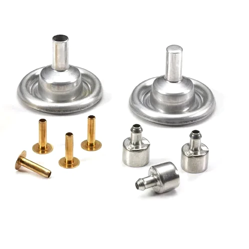
Hydroforming puts fluid pressure inside a tube or a closed preform and uses it to push the metal out into a die. What that buys, and the reason the process exists, is a smooth continuously varying three-dimensional contour that neither drawing nor stamping can produce in one piece. This page is about the capability and the geometry that justifies it.
A contour that changes section without a crease
The shape this process makes and others do not is one that transitions continuously – a dome that moves from a round section into a square flange without a crease, a shell with compound curvature in two directions, a form with no flat anywhere on it. A draw would need the part to be axisymmetric or near it; a stamping would need a seam or a series of facets. Hydroforming expands the metal into the die from the inside, so the section can change gradually all the way round.
The wall stays more even than a draw would leave it
In a deep draw the material is pulled over a punch and thins where it stretches most, and that is the limit on the draw ratio. In hydroforming the internal pressure supports the wall while it expands, so the thinning is distributed rather than concentrated. The practical result is that shapes with a depth-to-diameter relationship that would be marginal as a draw are achievable here without the intermediate anneals a draw would need.
Fewer pieces than a fabricated assembly
Where a compound-curvature shell would otherwise be made from several stampings welded together, hydroforming can produce it as one part. That removes the welds, the alignment fixtures and the finishing of the seams, and on a pressure-containing or cosmetic part those are usually the expensive operations. It is the reason the process is worth considering at all on parts that are not obviously complex.
What to put on the drawing to get the benefit
The drawings that suit this process specify the contour and its tolerances rather than a series of flat facets with radii between them. Datum schemes should reference the functional surfaces rather than convenient edges, because the part has no flat to sit on. And the trim line has to be defined, since the process needs a closed preform and the finished part has to be cut out of it.
How the contour is verified
The wall is checked along the contour rather than at a nominal point, and the finished part is measured on a CMM against the datum scheme the drawing specifies.
First articles and retention samples are kept for the programme, so a reorder is formed to the same contour and the same wall distribution. On a shape that no other process can make, that is what keeps the second batch fitting like the first.
This part belongs to our Deep Drawn Parts range, where the process notes and tolerance practice behind the whole family are collected.
Specifications
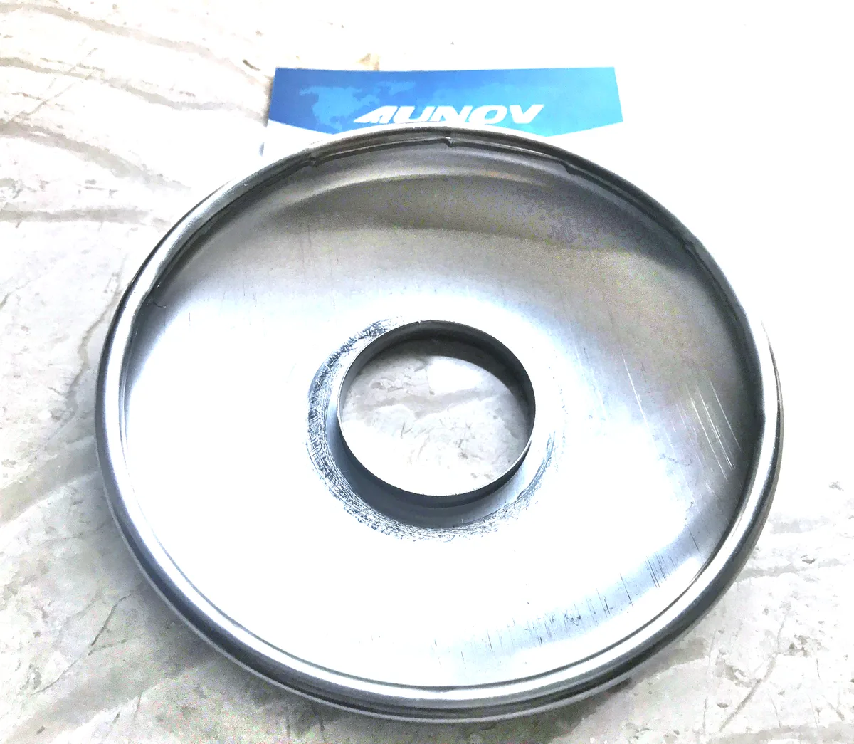
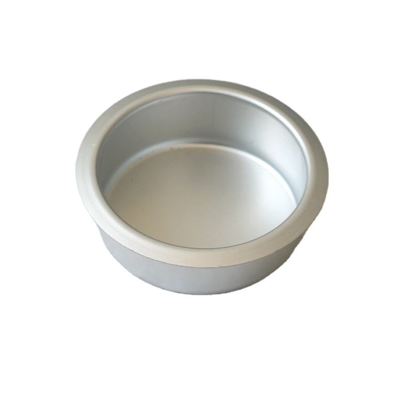
| Item | Custom Hydroformed Aluminum Dome Shell Caps |
|---|---|
| Brand | AUNOV |
| Designing | Made to your 2D/3D drawings (PDF, DWG, STEP, IGS) – a manufacturability review comes back with the quotation; revisions are re-quoted once rather than silently absorbed. |
| Tooling | Dies, fixtures and gauges are made in our own toolroom, so tooling lead time stays under our control, and ownership is confirmed on the quotation. |
| Samples | Samples are issued for approval before the run, so the approved first article becomes the gauge reference, and the signed sample is kept for future reorders. |
| Materials | Materials held include carbon steel, 304 / 316 stainless steel, aluminium and brass; special grades are sourced to the drawing when volumes justify. |
| Surface finish | Surface treatment matched to the duty: plating, coating or polishing; finish thickness and adhesion checked on the first article. |
| Processing | Tube or sheet preform, hydroforming into the finished contour, trimming, then annealing and finishing. |
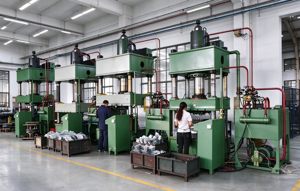
| Equipment | 5-250 T mechanical presses, 250-500 T hydraulic presses and annealing furnaces in line, with CNC turning centres for secondary operations and CMM inspection. |
| Tolerance | +/-0.03 mm on turned secondary features, +/-0.1 mm on as-drawn walls; GD&T per drawing, PPAP-style reports on request. |
| Delivery terms | Freight is quoted to your door in FOB, CIF or DDP terms, payment by T/T or L/C. |