
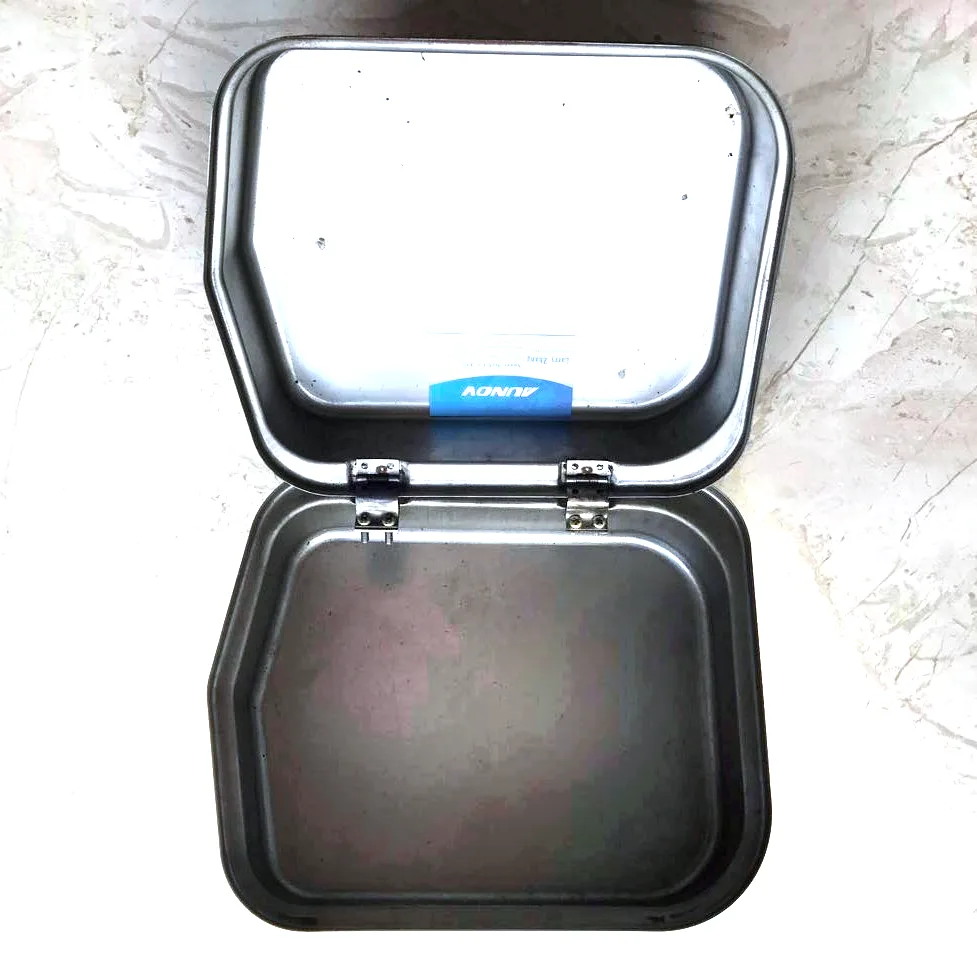
Drawn enclosures for electronics: the box is part of the circuit’s environment
An electronics enclosure is not packaging – it is thermal management, electromagnetic containment, mechanical protection and connector geography, all in one sheet metal part. A deep drawn sheet metal electronic enclosure box approaches those jobs from an advantage a fabricated box does not have: a one-piece shell with no corner seams, drawn in a single controlled sequence, so the electrical and thermal behaviour is consistent from the first box to the ten-thousandth.
This page is written for the engineer specifying an electronics housing: what drawn steel and aluminium boxes do for the board inside, which features should be formed versus machined, and where the honest limits sit.
Four jobs the drawn shell does for your electronics
Shielding. A seam-free box with a gasketed lid is a predictable Faraday cage. Welded boxes carry seam impedances that vary unit to unit; drawn shells do not. For radiated-emissions control, the win is at the lid flange – so we coin the flange flat and call out bare or conductive-finish zones where the EMI gasket lands. Shielding effectiveness of 40-60 dB from 30 MHz to 1 GHz is a realistic design target for drawn steel with conductive gasketing, validated by test house measurement on first articles.
Thermal path. Aluminium boxes spread heat from hot components to the walls; the drawn shell is the heat sink geometry. Wall thickness 1.2-2.0 mm in 3003 or 5052 conducts usefully, and internal standoffs can be lanced from the base to lift boards into the airflow the lid movement creates.
Protection. Drawn corners and a compressed gasket reach IP54 comfortably; IP65 is achievable with a tongue-and-groove flange design drawn into the parts. We state the ingress rating the design can honestly support after gasket-compression testing – not a number copied from a catalogue.
Connector geography. Gland holes, D-connector windows, and switch cutouts are pierced after drawing at ±0.2 mm position, deburred, and where a connector needs a ground path, the surrounding zone is left conductive. Machined spot-faces for connector panels hold ±0.05 mm.
Size range and construction choices
- Single-drawn boxes up to ~250 mm longest side; deeper units as drawn body plus drawn or stamped lid, flange-mated.
- Walls 0.8-2.0 mm – SPCC/DC01 for painted builds, 304 stainless steel for wash-down, aluminium 3003/5052 for thermal and weight.
- Lid systems: screwed flange with neoprene gasket (the default), quarter-turn latches for serviceable units, or conductive EMI gasket strips for shielding builds.
- Internals: lanced standoffs, PEM press-in studs, din-rail clips – fitted in-house after drawing so the box arrives ready for the board.
Design notes that save money at this scale
Draw the box deeper, not the flange taller. Extra depth is nearly free in the die; extra flange width fights the draw ratio and the price. If you are deciding between the two, depth wins.
Put connectors on the flange half, not the deep-drawn wall where possible. Piercing near a drawn wall distorts positions; the flange is the tolerant surface.
Decide the gasket before the finish. Powder coat on a gasket face is 0.08 mm of compressible paint where you wanted conductive metal – finish drawings mark masked zones explicitly, and the masking is quoted as a line, not absorbed.
Volume decides single-drawn versus body-and-lid. Under ~2,000 units a year, a smaller single-drawn box with a bigger machined panel may beat a large custom draw on total cost. The quotation shows both routes when they are close.
Tolerances and verification for electronics housings
- Body OD ±0.4 mm; flange flatness 0.3 mm per 150 mm as-drawn, 0.1 mm coined under gaskets.
- Cutout positions ±0.2 mm; spot-faced/machined features ±0.05 mm.
- Verification per first article: dimensional layout, gasket compression map with the real lid, shielding attenuation test (on request, at a partner lab), salt-spray for outdoor builds, and film-thickness readings on coated zones with masked-area checks.
Where these enclosures are working
- Industrial control and PLC expansion boxes – drawn steel, e-coat plus powder, gland plates machined in-house.
- RF modules and telecom edge devices – aluminium, conductive conversion finish, EMI gasket lids.
- LED driver and ballast housings – aluminium for heat spread, IP54 gasketed lids.
- Medical device modules – 304 stainless steel, wipeable, seam-free corners for hygiene.
Questions we are asked about drawn electronic enclosures
Can you hit our shielding specification, and how is it proven?
40-60 dB across 30 MHz-1 GHz is a workable design target with a drawn shell plus conductive gasket. Proof comes from measurement at a partner test house on first articles – we arrange it and hand you the report with the dimensional layout.
Will you hold cutout positions to our PCB connector tolerances?
±0.2 mm pierced, ±0.05 mm machined. Send the board outline and connector datums; the enclosure drawing will reference them directly so tolerance stack never has to be argued about.
Aluminium or steel for an outdoor electronics box?
Aluminium when heat or weight drives; steel when impact and cost drive, with e-coat plus powder for corrosion. Both are quoted with the finish system named so the comparison is real, not steel-price-versus-aluminium-price theatre.
What we need before quoting an enclosure
Send the enclosure drawing (or the board outline plus connector plan if the box is not designed yet), volume, environment and target ingress/shielding ratings. The quotation includes the die sequence, finish system with masked zones, and validation plan – engineering first, then price.
If you are weighing drawing against machining or welding for this geometry, the guide to deep drawn covers sets out where each route wins; the full Precision Deep Drawn Parts range is linked from the overview page.
Specifications
| Item | Deep Drawn Enclosure Box with Hinged Lid |
|---|---|
| Brand | AUNOV |
| Designing | Send drawings, or send a sample to be measured – samples are reverse-measured into a controlled drawing; revisions are re-quoted once rather than silently absorbed. |
| Tooling | Tooling is quoted once and held – reorders are priced on the part, not on the die. |
| Samples | Pre-production samples come with a full inspection report, so the sample is retained as the master, and later batches are gauged back to the signed sample. |
| Materials | Carbon steel (SPCC / DC01), 304 / 316 stainless steel, aluminium, brass and copper – the grade is matched to the duty of this enclosure. |
| Surface finish | The print decides between natural, plated or coated; we log the agreed finish and check thickness and adhesion on the first article. |
| Processing | Deep drawing on maintained presses, blank size and lubrication logged per run; every stage is logged against your part number. |
| Equipment | 5-250 T mechanical presses, 250-500 T hydraulic presses and annealing furnaces in line; first articles and batch samples are checked on the CMM. |
| Tolerance | +/-0.1 mm general on drawn sections, +/-0.03 mm on machined seats; GD&T per drawing, PPAP-style reports on request. |
| Delivery terms | Incoterms FOB as standard with DDP on request; sea and air options priced with the order. |
Related Products


Request a Quote for This Part
Send a drawing or sketch — get material advice, tooling cost and a per-piece price within 24 hours (working days).