
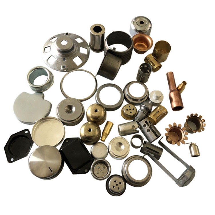
Brass and steel do not share a die: separate clearance and radius each
When a family of caps and cups spans both brass and steel, the tempting shortcut is one die set run twice. It does not work, and the reason is arithmetic. Punch-to-die clearance in drawing is a percentage of sheet thickness, but the right percentage depends on the material’s flow strength and work-hardening behavior, and brass and low-carbon steel differ enough that a clearance tuned for one produces visible defects in the other. A clearance that suits SPCC or DC01 steel is tight for cartridge brass: brass flows at lower stress, galls more readily against steel tooling, and under tight clearance it work-hardens fast at the draw radius and tears in the corner. So each material gets its own tool path, even for identical geometry:
- Clearance per material: roughly 7 to 10 percent of thickness per side for steel cups, opened toward 10 to 15 percent for brass depending on grade, fixed on the first article.
- Draw radii per material: brass tolerates a slightly smaller punch radius at equal thickness because it stretches further before thinning – but it punishes a rough radius far sooner. Our brass dies get a finer polish and a shorter re-polish interval, by stroke count rather than when parts start looking wrong.
- Lubrication per material: steel draws on conventional chlorinated or polymer drawing oils; brass runs better on sulfurized or pigmented lubricants that resist the galling brass is famous for, and the choice interacts with whether parts will be degreased for soldering or plating afterwards.
- Springback allowance per material: brass recovers more elastically than mild steel after a bend, so any formed feature – bead, lip, flange – carries a different overbend in brass than in steel for the same angle.
Forming brass: work hardening rate and when interstage annealing pays
Brass work-hardens faster than low-carbon steel per unit of strain, and that single fact shapes the whole draw plan. A C260 cartridge brass sheet roughly doubles its flow strength between annealed condition and 40 percent cold work; the same span in DC01 might raise strength 50 to 60 percent. In a single-stage shallow cap this does not matter – the part finishes before the material runs out of ductility. In a deep cup or a multi-redraw family, brass exhausts its formability sooner, and the failure arrives as a corner tear at the punch radius on the next redraw, or circumferential splitting at the rim where accumulated hoop strain finally exceeds the limit.
Interstage annealing is the standard answer, and the decision is economic as much as technical. Our rule for drawn brass cups: plan an anneal when accumulated reduction across stages exceeds roughly 60 to 70 percent of the material’s available draw ductility – in practice, after the second or third redraw for most cup proportions. The anneal, a bright anneal in protective atmosphere so parts come out clean and skip the pickling that would eat dimensional control, restores the ductility bank but resets strength: an annealed brass cup is soft, dents in handling, and the route afterwards needs gentler transfer and sturdier locating. That handling cost plus the furnace cycle is why we model the reduction plan before cutting the first die – sometimes one extra redraw is cheaper than one anneal, and sometimes annealing once beats three extra stages.
Springback difference between C260 brass and DC01 steel on the same profile
Give the same cap profile to brass and steel and the finished parts will not match, even with perfect tooling. Brass’s elastic modulus is around 100 to 110 GPa against steel’s 210 GPa, and springback scales roughly with yield strength over modulus: brass yields at comparable stress but is half as stiff, so it recovers roughly twice the elastic deflection when the punch releases. On a drawn cup wall this shows as a slightly flared, open mouth – the brass rim springs outward where the steel rim stays put – and on any formed flange or bead it means the brass part’s angle sits several degrees further from the formed angle than the steel part’s.
The consequences run through the family:
- Mouth flare on deep cups is the classic brass cup issue – a rim that measures oversize at the mouth and on-size at the wall. Where the drawing needs a controlled rim, a sizing or ironing pass after the final draw closes it; where the rim welds or crimps into the next assembly, the flare is harmless and we do not sell an operation nobody needs.
- Flange angle control: a brass cap with a mounting flange gets a larger overbend in its forming die than the steel twin, set from a measured springback trial on the actual coil lot, not a handbook.
- Mixed-family gauging: when brass and steel versions ship in one family, the gauges differ – same nominal, different go/no-go limits, because both parts must land inside the drawing band from different springback baselines. The gauge plan lists them separately; a common gauge on a mixed family is how a good steel part gets scrapped and a bad brass part passes.
Die wear and polishing: brass galls differently than steel
Tooling wear economics differ between the two materials. Steel, with a good drawing lubricant, wears dies gradually and predictably – die rings open slowly, cups grow slowly, wear shows first as diameter drift at the rim. Brass is less kind: it is the textbook galling material, transferring zinc-rich smears onto the die land under pressure, and once a transfer layer starts it feeds on itself – the smeared die surface tears the next cup’s surface, which smears the die worse. A brass die that is misbehaving does not drift; it goes from good parts to scored parts within a shift.
Prevention is cheaper than rescue, and our brass tooling practice is built around it. Die lands and radii on brass tools are polished finer than steel tools, and the draw radius is maintained at a mirror finish, because surface roughness is where the transfer starts. Re-polishing is scheduled by stroke count from the tool record, with the count set by the measured wear history of the first production run. The zinc smear has a second cost beyond tooling: a galled brass cap carries embedded die material and torn surface metal in its worst spots, and no cleaning process fully recovers a torn surface.
Choosing brass over steel when the cap must carry current or solder
The mixed family exists because the two materials solve different problems, and the choice per part should be functional, not traditional. Brass earns its price premium – typically two to four times the steel equivalent in material cost – on duties steel handles poorly. Electrical conductivity: C260 brass carries roughly 28 percent IACS against 10 to 15 percent for low-carbon steels, so a cap that is also a current path – a terminal cup, a battery contact shell, a ground stud surround – is often brass almost by physics. Solderability: brass takes solder directly with mild fluxes where steel needs plating first; a cup that will be solder-sealed into an assembly saves an entire process step in brass.
Steel wins its share honestly. Structural duty – clamp load, pressure, impact – belongs to steel’s higher strength at the same thickness, and a steel cap can run thinner than the brass equivalent for equal stiffness, partially paying back the conductivity trade. Cost at volume: when the cap’s job is purely mechanical enclosure, steel’s material and forming advantage is decisive, and zinc plating covers its corrosion weakness for a fraction of brass’s premium.
How we verify cap geometry across a mixed brass and steel family
Verification on a mixed family has to respect that the two materials answer the same gauge differently:
- Per-part-number gauge plans. Each variant carries its own dimensional plan and gauge limits, with the springback baseline recorded per material. Acceptance is always against the drawing band, never against the sibling material’s numbers.
- Mouth and rim geometry on deep cups: rim diameter and flare profile at a minimum of four positions, with the brass cups’ known mouth-springback pattern specifically bounded by the gauge.
- Wall thickness stations – rim, mid-wall, corner radius – per part, by ultrasonic or section on first article. Corner thinning acceptance differs by material: brass tolerates more stretch before tearing but shows orange peel sooner at coarse grain, so the corner reading pairs with a surface check.
- Surface condition on the draw radius band of every brass part – visual against a boundary sample for galling, zinc smear and orange peel – plus a sectioned first article per new brass tool to confirm grain size against the anneal target.
- Material verification by lot: brass and steel lots segregated physically and by paperwork; an XRF spot check on mixed shipments confirms the right cups are in the right bins, because a steel cup in a soldering fixture is a process failure no tolerance catches.
- Traceability per heat and grade: mill certificates mapped to part number and batch, with plating or solderability requirements on the same record.
- First-article dimensional report per variant, with die settings – clearance, lubricant, overbend, anneal position – archived per part number so a reorder of either material rebuilds its own route exactly.
Drawing, machining and welding each win on different geometries; the guide to deep drawn covers works through those boundaries, and the full Precision Deep Drawn Parts range is reachable from the overview page.
Specifications
| Item | Assorted Deep Drawn Caps and Cups Brass and Steel |
|---|---|
| Brand | AUNOV |
| Designing | Share your print, or send a part to be measured, our engineers reply with a manufacturability assessment and pricing. |
| Tooling | Tooling designed and cut in house, with your part number on the tool record. |
| Samples | First-article samples of the cup ship with a dimensional report and material certificate. |
| Materials | Stock for this part leads with brass, alongside carbon steel (SPCC / DC01), 304 / 316 stainless steel, aluminium and copper, with the final grade confirmed at the drawing review. |
| Surface finish | Finish options: plating, e-coat, powder coating, anodising or passivation, per your print. |
| Processing | Multi-stage drawing, annealed in line where wall thinning calls for it, then pierced and CNC-machined in house. |
| Equipment | Mechanical presses 5-250 T and hydraulic presses 250-500 T, CNC turning and milling cells, a climate-controlled CMM room. |
| Tolerance | +/-0.1 mm on as-drawn features, +/-0.03 mm on machined features. |
| Delivery terms | Standard terms FOB, DDP offered to EU and US, T/T and L/C accepted, D/P for established customers, call-off schedules and blanket orders supported. |
Frequently Asked Questions
Why can brass and steel not share a die even for identical geometry?
Punch-to-die clearance depends on the material’s flow strength and work-hardening, and brass and low-carbon steel differ enough that one clearance produces defects in the other. A clearance tuned for steel is tight for brass: brass flows at lower stress, galls against tooling, and tears in the corner.
How does springback differ between C260 brass and DC01 steel?
Brass work-hardens faster per unit strain, so on the same profile it relaxes off the tool differently than steel and must be restruck or sized to land. The restrike, not the first draw, is the control.
When is brass chosen over steel for a cap?
When the cap must carry current, solder, or simply look right in a brass assembly; steel wins on cost and strength. Each material gets its own tool path even for the same shape.
How are mixed brass-and-steel caps verified?
Cap geometry is checked across both materials with the correct clearance and radius per metal, and the typical minimum order is 1,000 pieces with a 24-hour quotation.
Related Products

Request a Quote for This Part
Send a drawing or sketch — get material advice, tooling cost and a per-piece price within 24 hours (working days).