
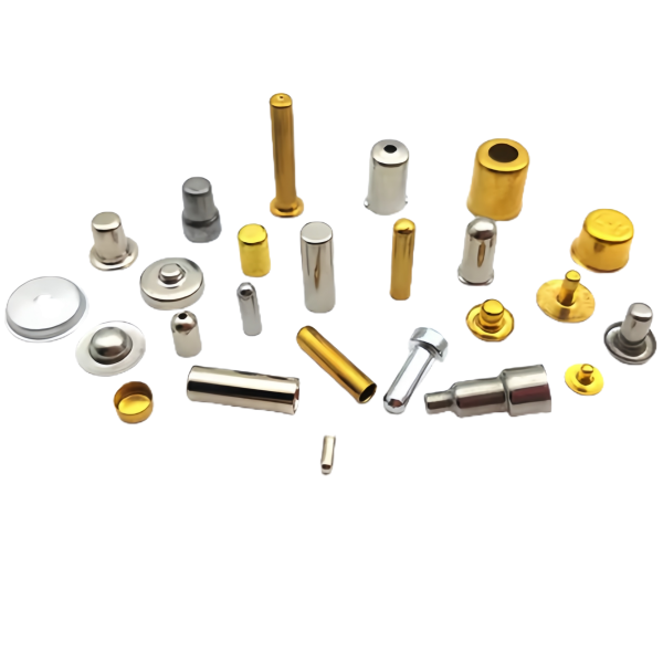
The Assorted Brass and Steel Deep Drawn Plug Shells family covers the small closed and open-ended shells that get pressed or threaded into a housing to blank off, locate or protect an internal feature. On paper a plug is the simplest part in a catalogue; in practice it is one of the least forgiving, because almost every plug works by generating an interference fit, and an interference fit is a wall-thickness problem disguised as an outer-diameter problem. This family also mixes two very different metals – brass for conductivity, thread compatibility and non-sparking duty, steel for strength and cost – and the two behave differently in the die, in the plating line and in the customer’s assembly. What follows is how we set up each of those, and how we verify a plug shell before it goes into the press-fit bin.
A plug seals by interference, so the shell wall is the seal
Most people specify a plug by its outside diameter and tolerance. That is necessary but not sufficient, because a plug holds by line contact along its cylindrical band, and the retention force it develops is a function of wall thickness and material, not just the diameter callout. A thin-wall plug pressed into a bore behaves like a spring: it deflects inward under insertion load, the line contact pressure drops, and the plug can walk out under vibration even though it measured in tolerance. A thicker wall holds its diameter under load and keeps the interference pressure up across the whole engagement length.
The numbers we work to, and why:
- Wall thickness is held as a ratio to diameter rather than as an absolute. On plugs under about 6 mm diameter we keep wall above roughly 0.5 mm where the application allows, because below that the retention force becomes unacceptably sensitive to a few thousandths of diameter.
- Outer-diameter tolerance is a stack of the drawn size plus any post-operations. We publish the as-pressed dimension against the bore the customer actually has, not against the nominal, so the interference band is agreed before the first production run.
- Roundness and cylindricity are verified on the sealing band specifically, not at the flange or mouth, because a plug that is lobed on its band leaks or walks even when every diameter on the print is in tolerance.
Brass and steel in one plug family: why they never share a die
When a single order carries both brass and steel plug shells, the temptation is to run one tool set and change the strip. We do not, because the two materials demand different blank-holder pressure, different draw radii and different lubrication. Brass has a lower yield strength and flows more readily, so it wrinkles in the flange at holder settings that steel needs to avoid tearing; steel needs more force and a tighter punch-to-die clearance to control the wall. Running them on shared tooling means one metal is always near a forming limit, and the scrap shows up as flange wrinkles on brass and punch-radius fractures on steel.
- Brass is annealed more aggressively between stages because its work-hardening rate climbs quickly, and a plug that is drawn hard tears at the wall on the second hit.
- Steel is run with a tighter clearance and a coating-resistant lubricant, since a bare carbon-steel blank galls where brass would slide.
- Die clearances are set per material and logged, so the press crew does not “compromise” a shared tool to the middle and produce a mixed-quality lot.
Closed-end versus open-end plugs and what each one is actually for
A closed-end plug forms a bottom, and that bottom is either a sealing face, a stop shoulder or a bearing surface. An open-end plug is a sleeve that must clear something – a shaft, a tube, a threaded stud – and its wall is the only thing carrying the load. The drawing route differs: a closed-end plug is drawn to a bottom whose thickness we can predict and control, while an open-end plug is drawn and then trimmed, and its two ends must stay parallel and concentric or it will not assemble.
- Closed-end bottom thickness: held by controlling the final ironing or by a light restrike, because a bottom that is too thick shifts the insertion depth and one that is too thin collapses under the insertion load.
- Open-end parallelism: the trim operation sets both ends, and we hold squareness so the plug seats fully without rocking.
- Burr direction: confirmed at review, because a burr that faces the insertion side gouges the bore the customer is pressing into.
Lead-in chamfer and press depth: the two numbers that decide assembly force
A plug that requires excessive press force is a plug the customer will complain about even though it is geometrically perfect. The insertion force is set by the interference, the engagement length and the lead-in geometry. A generous lead-in chamfer on the entering edge lets the plug start into the bore and self-align before the full band engages; without it, the first millimetre of insertion has to fight the full interference and the plug can gall the bore or push plating ahead of it.
- Lead-in chamfer angle and length are specified on the drawing as functional, not cosmetic, and we treat a chamfer outside tolerance as a reject.
- Engagement length is a design conversation: more length holds better but multiplies insertion force, so we help the customer pick the shortest band that meets the retention target.
- On plated plugs we account for plating build-up inside the chamfer, because coating accumulates at the lead-in edge and changes the effective start geometry.
Galvanic pairing when a brass plug meets a steel housing
Placing a brass plug into a steel housing creates a galvanic couple in any environment with an electrolyte, and the severity depends on the relative areas and the electrolyte. The plug is small and the housing is large, which is the favourable ratio, but the brass is the less noble metal in the couple and will preferentially corrode if the interface stays wet and conductive. This is a material-selection conversation we raise at quotation rather than an afterthought at field failure.
- Where the assembly sees moisture, we discuss isolating coatings or a plating choice on the plug that narrows the potential difference.
- Threaded brass plugs in steel ports are a known galling and corrosion combination; we discuss a compatible thread lubricant or a plated thread at review.
- For food or wash-down duty the brass grade itself is a decision, since leaded brasses that machine well are not always the right call where leaching is a concern.
How we verify a plug shell before it goes into the press-fit bin
Verification on plugs concentrates on the band that does the work, because a plug that measures fine at the mouth can still fail at the sealing surface. Each release is checked against these criteria:
- Sealing-band dimensions: outer diameter, roundness and cylindricity measured on the functional band with the part supported so it is not squeezed out of round by the gauge.
- Wall thickness at the band by section on the first article and by ball-micrometer on production samples, since wall thickness is the driver of retention force.
- Bottom or end condition: closed-end thickness and flatness, or open-end squareness and parallelism, as the type requires.
- Lead-in chamfer form and size confirmed against the print, because assembly force is a function the customer will feel.
- Material and finish certificates per lot, with plating or passivation records attached, and burr direction confirmed on a sample from each end of the run.
- Fit check: on the first article, a plug is pressed into a gauge bore replicating the customer’s actual mating hole and the insertion force is recorded, so the retention is proven, not assumed.
First articles and retention samples are kept for the life of the programme, so a repeat order starts from a measured baseline. On a part this small and this interference-critical, that baseline is the difference between a plug that holds and one that eventually walks out of the housing in the field.
Our deep drawn covers guide puts numbers to the design decisions behind a part like this — draw ratio, wall thinning, radii and trim; the Precision Deep Drawn Parts pages collect the rest of the family.
Specifications
| Item | Assorted Brass and Steel Deep Drawn Plug Shells |
|---|---|
| Brand | AUNOV |
| Designing | Share your print, or send a part to be measured, a manufacturability review comes back with the quotation. |
| Tooling | Our own toolroom designs and builds every die, stored under your part number. |
| Samples | Pre-production samples ship with dimensional data plus material certs. |
| Materials | Stock for this part leads with brass, alongside carbon steel (SPCC / DC01), 304 / 316 stainless steel, aluminium and copper, with grade selection confirmed at drawing review. |
| Surface finish | Surface treatment per the drawing: plating, e-coat, powder coating, anodising, passivation, fixed at the drawing review. |
| Processing | Progressive deep draw stages with in-line annealing as the draw ratio demands, with piercing and finish machining under the same roof. |
| Equipment | Mechanical presses 5-250 T, hydraulic presses 250-500 T, CNC turning centres and a climate-controlled CMM room. |
| Tolerance | Drawn tolerances held to +/-0.1 mm, +/-0.03 mm on machined features. |
| Delivery terms | Standard terms FOB, DDP offered to EU and US, T/T and L/C accepted, D/P for established customers, call-off schedules and blanket orders supported. |
Frequently Asked Questions
Why is specifying a plug by outside diameter alone not enough?
A plug holds by line contact along its cylindrical band, and the retention force it develops is a function of the wall thickness and the material as well as the diameter callout. A thin-wall plug presses in easily and backs out easily, so both the diameter and the wall have to be stated for the interference to mean anything.
When is a closed-end plug right and when is an open-end one?
A closed end carries whatever needs containing and gives the face something to react against, while an open end suits applications where the plug is a sleeve rather than a stop and something has to pass through. They are different functions rather than different versions of the same part, and mixing them in one order changes the final operation rather than just the drawing.
What actually decides the force it takes to press the plug in?
Beyond the interference itself, the lead-in chamfer and how deep the plug is pressed. Those two are usually the cheapest things to adjust when assembly force is wrong, which is why they belong on the drawing with tolerances instead of being left to whoever sets the press.
Should there be any concern putting a brass plug into a steel housing?
Yes, and it is worth raising before rather than after specifying. Dissimilar metals in contact in the presence of an electrolyte set up a galvanic couple, and how much that matters depends on the environment and which of the two is left to corrode. It does not stop the pairing, but it does decide whether the plug or the housing is the sacrificial part.
Related Products



Request a Quote for This Part
Send a drawing or sketch — get material advice, tooling cost and a per-piece price within 24 hours (working days).