
CAPABILITY · PRESSES
Stamping & Forming Capacity
From 5-tonne high-speed progressive lines to 500-tonne hydraulic deep draws — matched to the part, not the other way round. Browse our full range of custom metal stamping parts.
Two Families of Machines, One Shop
Mechanical presses win on speed; hydraulic presses win on controlled drawing speed and depth. We run both, so the process route follows the part. Progressive dies run on 5–250 tonne mechanical lines for high-volume stamped and lightly drawn parts, while 250–500 tonne hydraulic presses pull deep, thin-wall shells that mechanical motion would tear.
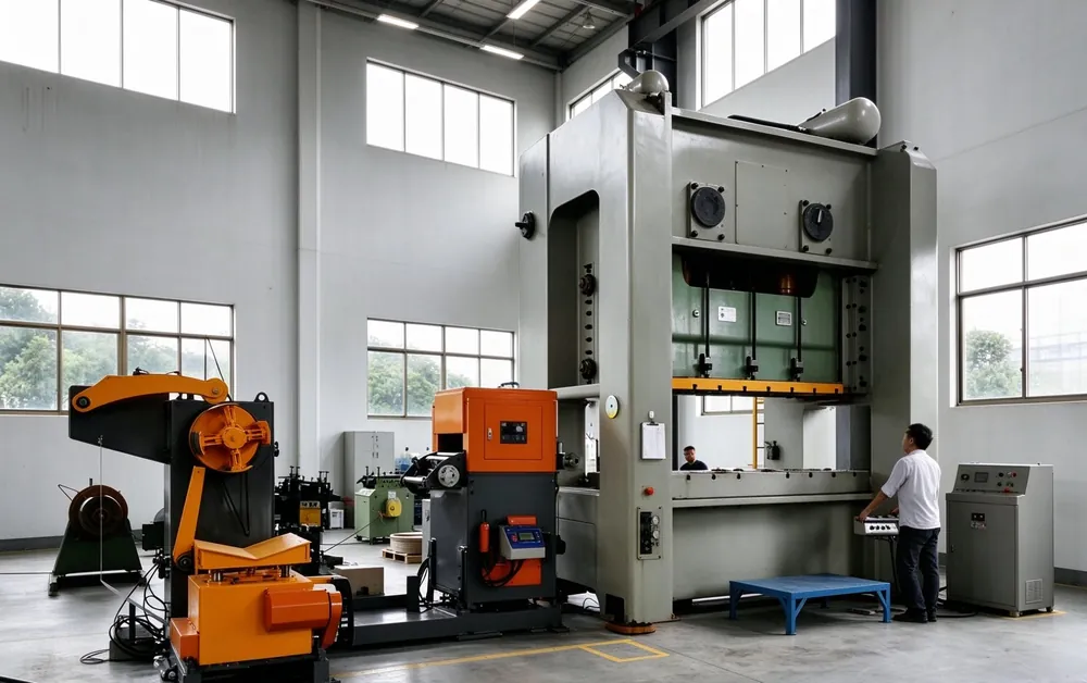
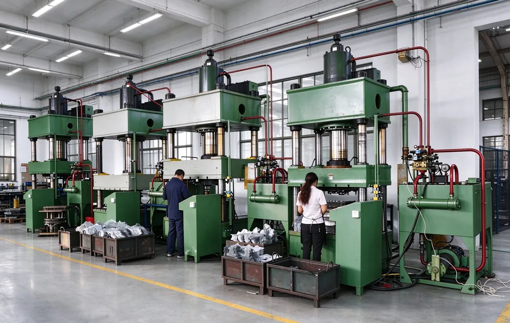
Multi-Stage Forming Under One Roof
Complex parts move through redraw, ironing, piercing, extruding and coining stages — each staged by our own tooling group so that tolerances accumulate correctly instead of drifting between vendors. Because the die shop, the presses and the inspection lab share one floor, a dimension that is drifting is caught at the press, not at the customer’s incoming check.
Typical cycle: coil in → progressive stamp or deep draw → CNC trim → wash → heat treatment or surface treatment where specified → final inspection → export packing.
What We Stamp and Form
Every stamping and forming job starts with the stock, and the stock decides what the tool can do. We run low-carbon deep-drawing grades (DC04, SPCC) for parts that have to draw without splitting, austenitic 304 and 316L stainless steel for corrosion duty, ferritic 430 where magnetic behaviour matters, and the 5xxx aluminium series (EN AW-5052, 5754) together with 3003 for lightweight housings that still need to draw. Brass (C26000 dead-soft) and copper (C11000) cover the conductive and decorative end of the range. Coil and sheet run from 0.15 mm to 3.0 mm, so the same shop handles a 0.2 mm sensor shim and a 3 mm structural bracket without changing suppliers.
One aluminium rule is worth stating plainly. The 5xxx series draws well, while 6xxx grades such as 6016 and 6014 are limited to shallow draws or internal high-pressure forming unless the part is aged to T6 afterwards; 6061-T6, with an elongation around 12–17%, does not deep draw at all. When a drawing calls out a 6xxx alloy for a deep shell we flag it before the tool is cut, because that is a design conversation, not a production problem.
From Coil to Packed Part
A formed part rarely comes off one hit, and the route we quote is the sequence the part actually needs rather than the shortest one we can get away with. Coil goes in, gets blanked and pilot-pierced in the progressive die, takes its first draw, is redrawn where the geometry calls for it, is ironed where wall thickness has to come down, then trimmed, pierced, coined or extruded before washing, heat treatment or surface treatment where the specification asks for it, final inspection and export packing.
Each redraw pass removes roughly 20–30% of the diameter it is handed, so a shell that needs four passes is quoted as four passes. Once the height-to-diameter ratio passes about 2, an intermediate anneal at 650–900 °C sits between passes to restore ductility before the metal is asked to move again. Ironing thins the wall deliberately — 20–35% reduction on steel, 30–50% on aluminium, brass and copper — which is how a thick blank becomes a thin-wall shell without adding material or weight.
Because the die shop, the presses and the inspection lab sit on one floor, the handoffs between those stages are internal. A drifting dimension is caught at the press that made it instead of at the customer’s incoming check three weeks later, and the tool change that fixes it is scheduled by the same people who cut the tool.
Tolerances We Hold, and How We Prove Them
A tolerance is only worth the measurement behind it. In-dial features are held to ±0.02–0.05 mm depending on the feature and the material, and wall thickness to ±0.05 mm, tightening to ±0.02 mm after ironing. Outside diameter runs ±0.10 mm at general tolerance and ±0.05 mm on controlled features, part height ±0.15 mm and ±0.10 mm, wall thickness ±10% and ±5%, and concentricity 0.10 mm and 0.05 mm. As-drawn surfaces leave the press at Ra 1.6–3.2 µm; where the drawing asks for smoother, electrolytic polishing takes that to 0.1–0.8 µm.
Where a characteristic is safety-related or sealing-critical we would rather agree the measurement method with you up front than argue about it at goods-in. Pressure-decay and helium leak testing are reported against your own specification, in the units you asked for, rather than as a pass/fail line on our own paperwork.
The Defects We Design Out Before the Tool Is Cut
Most stamping and forming failures are already visible in the tool design. Tearing at the cup wall almost always means the limiting draw ratio was pushed too high — roughly 2.0–2.3 for low-carbon and IF steel, 1.9–2.1 for stainless steel and 2.0–2.2 for 5xxx aluminium — and the correct answer is another redraw pass, not more tonnage. Wrinkling in the flange points at blank-holder force instead, normally 2–4 MPa on steel and 0.8–1.5 MPa on aluminium.
Earing on a drawn cup comes from planar anisotropy in the strip and is managed through blank shape and trim allowance rather than by stopping the press. Springback on bends is compensated in the tool geometry. Burrs are controlled by punch and die clearance together with a scheduled regrind, because a burr that grows quietly is a burr that ends up at the customer. Galling on stainless steel is handled with tool coatings and the right lubricant, picked for the alloy rather than for the price.
The economics are simple enough. An hour spent on the draw schedule before the tool is cut is cheaper than a week of scrap after it, which is why we review the blank, the reduction per pass and the anneal points with you before anything goes on a machine.
Stamping, Forming or Deep Drawing?
Progressive stamping suits flat and lightly formed parts at high volume, where the carrier strips the part through the die and cost per piece falls with every thousand units. Transfer and single-station tooling fits medium volumes and larger blanks that a progressive strip cannot carry cleanly. Deep drawing is the answer whenever the part is a shell — a cup, a can, a housing, a tube — because it forms a closed shape out of one flat blank instead of assembling it from several pieces and welding them together.
Plenty of parts need two of the three: a stamped flange on a drawn shell, or a progressive blank feeding a deep-draw station on the same line. That is precisely why we run mechanical and hydraulic presses, our own die shop and the inspection lab under one roof. The process route follows the part instead of the part being squeezed into whichever machine happened to be free, and the quotation you get back is the one the part deserves.
If you are not sure which route your part belongs in, send the drawing. We will tell you which of the three we would use, why, and what changes about the price if the geometry moves — before you commit to a tool.
Continue through the capability tour: the deep drawing process, tool & die design and quality control.
Talk To Our Engineers
Send your drawing to [email protected] — material advice, tooling plan and a per-piece price within 24 hours.
Stamped and formed parts
- Oxygen sensor frame
- Stamped Round-Base Mounting Bracket
- Stamped End Cap with Side Hole
- Wiper Motor Cap with Shaft Boss
- Custom Multi-Hole Stamped Mounting Bracket with Locating Bosses
- Black Powder Coated Stamped Sheet Metal Panel Frame
- Custom Bent Sheet Metal Stamping Bracket
- Progressive Die Stamped Formed Bracket for Automotive
- Deep Drawn Circular Motor End Cap Stamping
- Custom Spun Metal Flanged Ring Bearing Seat
- Stamped Steel Shallow Drawn Motor Cover
- Automotive Chassis Stamped Mounting Bracket
- Automotive Seat Stamped Mounting Plate
- Deep Drawn Automotive Seat Stamping Component
- Stamped Automotive Seat Side Bracket with Large Bore
- Copper Coated Clutch Backing Plate Stamping
- Deep Drawn Square Cover with Flanged Rim Zinc Plated
- Galvanized Stamped Angle Bracket with Circular Cutout
- Stamped Sheet Metal Frame Corner Connector
- Zinc Plated Stamped L Angle Brackets
- Stamped U-Shaped Clamp Bracket Galvanized Steel
- Stamped Triangular Gusset Angle Bracket
Tooling We Build In-House
Every die that runs on our presses is designed and built in our own toolroom, which is the quiet reason our tolerances hold. A die is not a catalog item you buy and hope about; it is a custom tool whose clearances, radii and springback compensation are tuned to one specific part and one specific grade. We own that whole loop, from first CAD layout to the first tryout stroke.
Owning tooling matters most when something drifts. If a dimension walks out of tolerance mid-run, our toolmaker is on the same floor as the press, not a time zone away. The correction happens in the die, not in a band-aid on the part, and the next thousand pieces come out right.
Lead Time and Capacity Transparency
We quote lead time against a real production ceiling, not a promise that sounds good on a sales call. A new progressive die takes longer than a new bracket because the die is the product, and we would rather tell you that up front than surprise you at shipment. Tooling lead time is stated at quote, and repeat parts run inside a reorder window your planning team can actually use.
The same honesty applies to capacity. Our tonnage range, from 5-tonne high-speed lines to 500-tonne hydraulic draws, sets a real ceiling on weekly output. When a program scales, we tell you the ramp schedule before you commit volume, so your line never starves while we run the next coil.
Quality System: SPC and First-Article
A tolerance is only as good as the measurement behind it, so we do not stop at the dial indicator. We run statistical process control on the features that matter, watch the control chart for drift, and trigger a correction before the drift becomes scrap. First-article inspection is a gate, not a formality: the first piece of a run is measured against the drawing and signed before the press is released to speed.
For automotive and other regulated programs we work to IATF 16949 discipline and supply PPAP packages at the level your launch needs. For commercial work we apply the same SPC and first-article habits without the full paperwork. Either way, the part is measured at the points that matter, not just the easy ones, and traceability runs from coil to carton.
Secondary Operations and Finishing
A formed part rarely ships as it leaves the press. We tap, weld, deburr, insert fasteners, passivate stainless steel, and coordinate plating or powder coat without the part bouncing between vendors. Folding these into the cell means one schedule, one quality record, and no freight between operations that can hide a defect.
The finish on a stamped part is a functional choice, not decoration. A welded seam on a housing needs a clean, burr-free edge to sit flat; a connector shield needs passivation so the contact does not corrode; a decorative cover needs a surface that hides the grain. We match the secondary step to what the part actually does in your assembly.
How We Quote a Forming Job
Send a STEP or DWG and we read it the way a toolmaker does: material, thickness, draw depth, hole positions, and the features that must never drift. From that we pick the process route, the die type and the press, then price the four things that actually cost money — tooling, material, press time and secondary work.
We quote quickly because the route is usually obvious to someone who runs all three processes under one roof. A flat bracket is a stamping; a closed shell is a draw; a feature that must be cut is a machining step. When a part could go two ways, we tell you the cost and lead time of each instead of forcing it into whichever press is free.
A Worked Example: Bracket to Drawn Shell
A customer came to us with a sensor assembly that was two welded pieces: a flat mounting bracket and a small drawn cup. We pulled them into one part. The blank was pierced and pilot-holed on a progressive press, then the centre was drawn into a shallow shell in a later station, leaving the bracket flange around it. One tool, one hit per part, no weld line to clean or inspect.
The trick was the sequence, not the tonnage. Draw the shell first and the outer holes distort; pierce first and the draw tears the edge. We ran the draw as the first forming stage, then finished the outer holes, so the stamped features and the drawn form agreed with the print on the first tryout. That is the kind of part that looks simple and punishes a shop that does not think through the order of operations.
Choosing the Route: A Quick Decision Table
When a new print lands, the first question is always the same: which route fits. This table is the filter we use in-house.
| The part is… | The route | Why |
|---|---|---|
| Flat, with holes and bends, high volume | Progressive stamping | Lowest per-part cost, one strip, many stations |
| Flat, simple, low volume | Compound or single-stage die | Cheaper tool, faster to prove out |
| A cup, can, housing or tube | Deep drawing | Forms a closed shape from one blank, no weld |
| Deep with thin, even walls | Deep drawing | Holds wall and concentricity a stamp cannot |
| A feature that must be cut to size | CNC machining | Removes material precisely where formed metal cannot |
| A mix of stamped and drawn features | Combined route | One coordinated line, fewer handoffs |
If the answer is not obvious, we say so and walk it through with you. The wrong route is the most expensive thing a buyer can unknowingly sign for.
Where Each Service Goes Deeper
This page is the overview; the specifics live one level down. If you know your part is a stamping, the custom metal stamping page covers die types, DFM and quoting in detail. If it is a shell or a tube, the deep drawn parts page goes into draw ratios, wall limits and tooling. If a feature must be cut, the CNC machining page explains tolerances and materials.
We would rather point you to the right page than pad this one. The value of one shop with three routes is that the handoff between them is ours to manage, not yours to chase.
The Five Basic Forming Moves
Every stamped or formed part, however complicated, is built from five moves. Blanking cuts the flat shape out of the strip. Piercing punches the holes. Bending folds the flat into an angle or a channel. Drawing pulls the metal into a cup or shell. Forming is the catch-all for the shapes that are none of the above — louvers, ribs, curls, embossing.
Most parts are a short recipe of these moves run back to back, and the craft is the order. A bracket is blank, pierce, bend. A shield is blank, form, pierce. A can is blank, draw, redraw, trim. Get the order wrong and each move fights the last; get it right and the metal work-hardens in a way the part can survive.
Choosing Material by What the Part Must Do
The grade is not picked from a list; it is picked from the job. A part that must draw deep without splitting wants a low-carbon drawing grade like DC04 or SPCC, because they flow before they tear. A part that must resist corrosion wants 304 or 316L stainless steel. A part where magnetic behaviour matters wants ferritic 430. A lightweight housing that still has to draw wants a 5xxx aluminium such as 5052 or 5754.
Copper and brass sit at the conductive and decorative end of the range, and the thickness decides how far any of them can go. Coil and sheet run from 0.15 mm to 3.0 mm, so the same shop handles a 0.2 mm sensor shim and a 3 mm structural bracket without changing suppliers. Name what the part must do and the grade usually names itself.
Beyond Tearing and Wrinkling: The Other Defects
Tearing and wrinkling get the attention because they are the loud failures, but the quiet ones cost just as much. Springback leaves a bend at the wrong angle after the part leaves the die. Twist curls a long thin part out of flat. A burr from a dull punch edge scratches the part next to it in the bin. A surface scuff on a cosmetic cover becomes a reject at incoming inspection.
We design these out the same way we design out tearing — in the tool, before the first stroke. Springback is compensated in the die angle, twist is balanced with proper blank layout, and burrs are kept away with punch-and-die clearance set to the material and thickness. The aim is a part that is right because the tool is right, not because an operator straightened it by hand.
Prototype to Production, Without a Rebuild
The jump from one prototype to a thousand is where forming programs stumble, so we plan it early. We prove the datum scheme and the die on the prototype, confirm the tolerances on a CMM, and only then scale the tooling. If your design is still moving, we keep the prototype flexible and tell you which tolerances will lock the die.
That conversation up front is cheaper than a re-cut die later. A forming tool is the product, and the cheapest time to change it is the day before it is cut, not the day after the first thousand parts show a flaw.
Automation on the Line
Volume work is not run by hand. Our coil-fed lines straighten, feed and stamp continuously, parts drop at rate, and inline stations handle the tapping, welding or plating that would otherwise bounce the part between vendors. The result is a line where the part is finished in one pass and the operator watches the control chart instead of wrestling the material.
Automation is not an add-on we sell; it is how the cost falls. Every manual handoff a part skips is a chance to drop cost and a chance to introduce variation. We automate where the volume earns it and keep the flexibility for short runs, because a shop that only runs one kind of line is not a partner, it is a machine.
The Design Handoff: Drawing to Die
The moment a drawing becomes a die is where most forming programs quietly succeed or fail. We read your print for the features that must never drift, translate them into die clearances, radii and springback compensation, and prove the first part against the drawing before the press is released to speed. A good handoff leaves nothing to interpretation on the shop floor.
Where a print is ambiguous, we ask before we cut steel. A missing tolerance, a radius that cannot be formed as drawn, a wall that fights the draw ratio — these are cheaper to resolve as a question than as a re-cut die. The best tooling starts with a clean conversation, not a clean-swept guess.
What to Look for in a Forming Partner
If you are comparing shops, look past the quote and check three things. First, does the tooling stay in-house, or does a drift in tolerance wait on an outside toolmaker? Second, can one supplier run stamping, forming and drawing, or will your part bounce between vendors who each point at the other? Third, is the inspection a CMM and a control chart, or a promise and a caliper at the end of the line?
These three tell you more than the price. A shop that owns its tools, runs all three routes and measures with a chart is one that can hold a tolerance at part one million on a Tuesday shift change. Everything else is a sales call.
The Industries We Form For
Automotive programs send us brackets, shields and terminals where the volume is high and the tolerance is watched with SPC. Sensor makers send housings and frames where the wall and the bore have to stay true for the element to seat. Appliance builders send panels and brackets that have to look good and fit a line that runs all day. Connector and electrical work brings shields and busbar sections where conductivity and a clean surface matter most.
EV work has grown into its own stream — busbars, cell housings and lightweight structural brackets that would have been cast or machined a few years ago. The common thread across all of them is the same: a flat blank, a right-first-time die, and a supplier who measures what the drawing actually demands. Send us the print and we will tell you which route fits before any tooling is committed.
What is the difference between stamping and forming?
Stamping is the umbrella for cutting and shaping flat sheet with a die, while forming is the specific action of bending, flanging or embossing the metal into a shape without drawing it into a shell. In practice a part is usually both: it is blanked and pierced (stamping) and then bent or formed (forming) in the same die.
Do you build the tooling in-house?
Yes. Every die that runs on our presses is designed and built in our own toolroom, tuned to the specific part and grade. That keeps tooling corrections on the same floor as the press, so a dimension that drifts is fixed in the die rather than on the part.
What is your lead time for a new forming tool?
It depends on the die and the part, but we state tooling lead time at quote before any steel is ordered. A simple compound die is quick; a multi-station progressive die takes longer because the tool is the product. We share the timeline up front so your planning can work around it.
Do you handle assembly after forming?
Yes. We tap, weld, deburr, insert fasteners and run inline assembly so a part can leave our floor ready for your line. Folding assembly into the cell keeps one schedule and one quality record, and it removes the freight and finger-pointing that come from splitting operations across vendors.
Do you offer design help before the die is cut?
Yes. We review your drawing for draw ratios, springback and features that add cost without adding function, and we suggest changes before any steel is ordered. A few minutes of design-for-manufacturing on the drawing is the cheapest place to save on a forming program, and it costs nothing to ask.
What is the difference between stamping and deep drawing?
Stamping cuts and forms flat sheet; deep drawing stretches sheet into a seamless cup or shell.
What press tonnage does Aunov use for stamping?
From 5T high-speed progressive lines up to 500T hydraulic presses.
Can Aunov run progressive die stamping?
Yes. Aunov builds progressive dies in-house for high-volume stamped parts.
What materials can Aunov stamp?
Stainless steel, aluminum, brass, copper and carbon steel.