
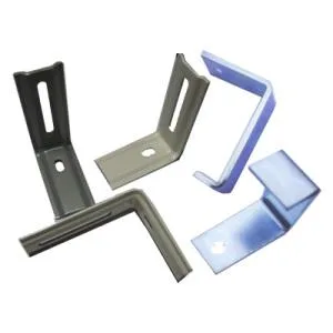
A bracket whose job is to move a load into a bolt circle
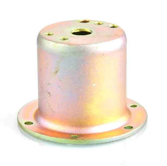
A stamped round-base mounting bracket looks like the simplest thing on a drawing: a disc, a cone or a shallow dome, and a flange with holes in it. In service it is anything but simple. The bracket has exactly one structural purpose, and everything about its shape follows from it: take whatever force the mounted component generates – torque from a motor, thrust from an actuator, alternating loads from a pump – and spread it into a ring of bolts so the fastener material, not the sheet metal, carries the stress.
That single sentence decides most of the design questions. Because a bracket is a load spreader, its geometry is dictated by the bolt circle and the moment arm, not by how it looks when drawn in plan view. We stamp these parts from coil in progressive dies, holding +/-0.05 mm on the bend positions and +/-0.1 mm on the blank outline, and in-house toolroom keeps the die dedicated to your part number so the tool history never gets separated from the job.
Why the cone is nearly always right
There are three common ways to get from a small feature in the middle to a bolted flange at the outside, and each behaves differently under load.
| Flat disc, constant thickness | Cheapest to form and easiest to blank. Carries load only through bending of the flat web, so stiffness scales with thickness cubed – reaching a given stiffness means adding steel, adding weight, or accepting deflection. |
|---|---|
| Stepped or walled disc | A vertical wall adds section depth without adding material. Good where axial space is tight, but the wall is a bending zone and it is where stress concentrates at the fillet. |
| Conical (drawn) base | The cone puts material exactly where the moment arm needs it, and the slope lets the load go from the central boss into the flange almost as a membrane action. For a given mass and thickness it is the stiffest of the three, and it is the shape we default to when the load is torque or reversing thrust. |
The practical consequence of the cone is worth stating plainly: a conical bracket can often be made from thinner, lighter material than a flat one for the same deflection. That is where the real cost sits, not in the steel price. If a customer asks us to go thinner on a conical bracket, we ask what the deflection limit actually is, because thickness on a cone buys stiffness very efficiently and the answer is often that the original spec carried more margin than the application needed.
The bolt circle is the real tolerance stack
Everything interesting about a mounting bracket happens between the bolt circle and whatever it is bolting to. If the mating part is a cast housing, a machined flange or a welded frame, there are three stacks in series:
- Position of the bracket’s own holes. Pierced in the flat blank before forming, so this is a blank-outline tolerance – +/-0.1 mm as a working figure, with the capability data available on request.
- Position of the mating holes. Frequently the worst term in the stack, because a casting is usually located by its own datum scheme and rarely agrees with the bracket’s ideal.
- Position of the central boss. Formed in a later station, so it inherits the datum movement of the whole flange plus its own forming error.
Where the design allows it, the way out is to make the bracket self-locating rather than fully constrained: a clearance hole plus a dowel or a spigot, or a slotted hole on one bolt in the circle so that the fastener can absorb the stack instead of the bracket fighting it. A slotted hole looks like a tolerance relaxation and is really a tolerance mechanism – the cost is that the joint can rotate slightly under reversing load, so it needs a defined tightening sequence and, where vibration is significant, a prevailing-torque feature.
Loosening, vibration and the fastener choice
Stamped brackets see vibration. In a vehicle or a machine, a bracket that is stiff but un-locked will develop the familiar rattle, and the rattle comes from micro-motion at the joint, not from the bracket deforming. Three things decide whether the joint stays put, and they are decided at the drawing stage:
- Bolt clamp load. The bracket sits between the fastener head and the washer face. Wide flat bearing areas raise the achievable torque without crushing the sheet. Serrated or embossed washer faces help in a painted or coated condition, where a plain face would need much more torque to reach the same clamp.
- Preload retention. Under vibration, plain bolts relax. Options range from a prevailing-torque type, to a nylon insert, to a spring washer, to applying a retaining compound at assembly. We do not choose this for the customer – it belongs with the assembly design – but we do make sure the bracket’s bearing surfaces can support whatever method is chosen, including the flatness that a spring washer needs to sit on.
- Joint stiffness ratio. A very stiff clamped member next to a very compliant one lets the soft side carry the movement and lose preload. This is the reason a thin stamped bracket sometimes needs a thicker section than the calculated load suggests.
On corrosion: carbon steel is the default and is usually zinc-plated or powder-coated. Where the bracket is inside a wet cavity or sees road salt, 304 or 316 stainless steel removes the coating variable entirely, at the cost of galling at the threads – which is a real problem for stainless steel fasteners and is why stainless steel brackets are often specified with a plating or with a nylon patch that gives the thread a defined friction. We quote plating, coating or polishing to suit the drawing, with alternatives costed alongside.
Flatness, forming and the springback you get for free
A flange that bolts up at four points needs to be flat enough that the fasteners do not have to pull it into contact. Forming a bracket from a flat blank naturally introduces springback, and a conical section springbacks more than a flat one because the material is bent through a larger angle. Three process details manage this:
- Bend sequence and over-bending. The flange is usually the last form, and it is over-bent slightly so that release lands on the nominal angle.
- Dowel or bead relief. Forming features located near the bolt holes constrain springback and hold hole position, which matters more for repeatability than the absolute angle.
- Coining or a sizing station. A final light press can bring flange thickness and flatness into a narrow band at modest cost, and it is worth it when the part is on a critical bolt pattern.
We press between 5 T and 250 T, with in-press forming and piercing, and check first articles and batch samples on the CMM. For a bracket, the sensible inspection focus is not the whole outline but the features that make the joint work: hole position relative to the boss, flange flatness, and the cone’s concentricity to the mounting axis. Those are the dimensions that go into the mating part’s tolerance stack, so they are the ones worth reporting on.
What a round base changes about surface finish
The finish specification on a round-base bracket is constrained by the fact that most of the part is a surface rather than an edge. A powder coat on a cone reads well and protects the full surface, but its cured film stands proud of the sheet, so any dimension that was held on the bare part has shifted by the film thickness – typically tens of microns, which is not nothing when the flange is being bolted to something. Plating has the same issue in reverse, since plating grows on a sacrificial layer and can be specified either for size after plating or before it. The only safe rule is to state which one the drawing means.
Where a datum surface has to stay absolutely as-drawn, masking is specified for it. On a bracket the surfaces that usually need masking are the flange face that bolts against the mating part and the bore or pilot that locates the bracket, because both are functional surfaces and both are the ones a coating would ruin. Masking also has to be thought about at the drawing stage: a masked area is an area that must be masked on every part, which is a manual operation or an added process step, and it is cheaper to know about during quotation.
Polishing is the finish to be careful with. A polished cone improves appearance and can help with cleanability, but polishing a formed surface also polishes the forming marks, and a visible difference in surface texture between the cone and the flange is a common cosmetic rejection. If the part is going to be polished, the drawing should say whether the whole part or only the flange is in scope.
Design review questions that save a tool charge
The manufacturability review that comes back with the quotation is the cheapest place to catch a problem. The questions that most often change a round-base bracket drawing are:
- Is the round base a clearance cover or a locating pilot? It changes whether the central feature is a clearance bore or a press or interference fit, and it changes the hole tolerance band entirely.
- Which bolt circle – through the flange, or through the cone wall? A flange bolt circle is pierced flat; a cone-wall bolt circle is pierced after forming and needs a flat spot or a boss.
- Is the bracket the sacrificial item in the joint, or the structural one? If it is sacrificial, its material should be chosen to fail first, which is a different design intent from choosing it to never deform.
- Does the assembly need a captive fastener, a hinge line, or a pivot? A bracket that also acts as a hinge puts its entire life in a small area of the bend, and the bend radius and grain direction then dominate the design.
- What is the actual environment? Bare interior, or underhood and wet? This decides whether coating is enough or whether the substrate has to be stainless steel.
Send drawings in PDF, DWG, STEP or IGS, or send a sample to be measured. The approved revision becomes the controlled master, samples are provided against the drawing, and production starts only after written sign-off. Delivery is FOB Ningbo or Shanghai with T/T or L/C, quoted in USD or EUR, and call-off schedules are supported – which suits a bracket, since brackets are usually the part that ships in steady small batches rather than in a one-off.
Parts like this one sit under the Custom Metal Stamping Parts range, whose overview page gathers the tooling logic, finishing options and tolerance notes shared across the family.
Where this part is used
A round-base mounting bracket is one of those parts that looks trivial on a drawing and turns out to be a structural component with a single job. The disc or shallow dome in the middle is where the mounted component sits; the flange with holes in it is how the load gets spread into a ring of bolts. Everything about the shape – the cone, the flange, the bolt circle – follows from that one function, and the sheet metal is only the material it happens to be made from.
You will find these brackets wherever a motor, actuator or pump has to be mounted onto something else through a bolt pattern: electric motors on machinery, actuators on industrial equipment, pumps on skid frames, and gearboxes on conveyor drives. The load is usually torque and vibration rather than a static weight, and the failure that gets reported is rarely the bracket tearing – it is the bolt loosening because the bracket was too compliant and the joint lost preload.
What we need to quote it
Send the bolt circle diameter and the number of holes, the material grade and thickness, and the load – force, torque, and whether it is steady or cyclic. The cone angle and the flange thickness follow from the load and the bolt circle, so we will confirm the geometry at drawing review rather than just quote the print. Tell us what the mounting surface is and whether the bracket is a thermal or galvanic isolate, because that decides the fastener material and sometimes the bracket’s own finish.
Specifications
| Item | Stamped Round-Base Mounting Bracket |
|---|---|
| Brand | AUNOV |
| Designing | Send drawings, or send a sample to be measured – a manufacturability review comes back with the quotation; the approved drawing is kept as the controlled master. |
| Tooling | Dies, fixtures and gauges are made in our own toolroom, so the die charge appears as its own quotation line, and the die remains dedicated to your part. |
| Samples | Sample lead time is quoted with the order, and the approved sample governs the run. |
| Materials | Carbon steel, 304 / 316 stainless steel, aluminium and brass are all held in stock; the final grade is fixed with the drawing review. |
| Surface finish | Plating, coating or polishing are matched to the duty; any alternative is quoted alongside the quotation, and sample approval is given in writing. |
| Processing | Coil-fed stamping, deburred and finished to the print; in-process checks sit between stages, not only at the end. |
| Equipment | Mechanical presses 5-250 T, in-press forming and piercing; first articles and batch samples are checked on the CMM. |
| Tolerance | +/-0.05 mm on bend positions, +/-0.1 mm on blank outline; GD&T per drawing, PPAP-style reports on request. |
| Delivery terms | FOB Ningbo or Shanghai, payment by T/T or L/C, quoted in USD or EUR; call-off schedules are supported. |
Related Products



Request a Quote for This Part
Send a drawing or sketch — get material advice, tooling cost and a per-piece price within 24 hours (working days).