
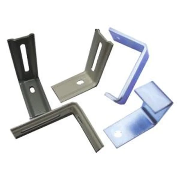
A family of L angles shares a die philosophy, not one die
This part is quoted as a family of L-shaped angle brackets in graduated sizes, in cold-rolled steel from 1.5 to 2.5 mm, and that description changes the engineering conversation entirely. A single bracket is a tooling problem.
There are three ways to run a family, and they have genuinely different economics. One is a dedicated die per size, which gives the best result on any individual part and the worst tooling cost across the family. Another is one die with changeable inserts, which costs more to design but far less to duplicate across sizes.
- Dedicated die per size — lowest risk per part, highest total tooling. Justifiable only at high volume per size.
- Insert die — punch and cavity inserts change with the size. Design cost is higher once, duplication cost is low thereafter. Usually the right answer above about three sizes.
- Size standardisation — the customer accepts a coarser size range. Cheapest by a wide margin, and it needs to be agreed at quotation, not after the first three dies are cut.
The material range in this family is 1.5–2.5 mm, and that matters as much as the size range. A die designed for 1.5 mm has different shut-off, different relief and a different wear profile than one for 2.5 mm. One insert covering a 1 mm thickness range will be optimised for one of those and compromised on the other.
Blue-white zinc on 1.5–2.5 mm consumes a different share of each tolerance
The finish here is blue-white zinc plating, and across a thickness family it has a disproportionate effect on the thin members. A zinc electroplate at 8–12 µm builds on both faces of a 1.5 mm bracket, adding 16–24 µm to a dimension measured across opposed faces.
That is worth stating concretely, because the same drawing tolerance means different things across the family. A ±0.10 mm hole position tolerance is comfortable on a punched part. A ±0.05 mm tolerance on a small hole in a 1.5 mm bracket with a 16–24 µm plating build is a third to a half of the band consumed before any plating variation.
- Undersize the features — punch holes and slots undersize by twice the nominal plating thickness on diameter. State the plating thickness on the drawing, because a range is not usable as a design input.
- Mask functional faces — any face that seats, gauges or slides against another part should be masked. A bearing face with 16 µm of plating on it is dimensionally different from a bare one, and that difference may be exactly what a sliding fit is tolerating.
- Thin-wall burr growth — burr on 1.5 mm stands roughly 0.04–0.08 mm, and a plating process that is not careful about the burr will plate over it rather than plate around it, producing a lifted edge that fails an adhesion check.
- Coverage on cut edges — the cut edge on 1.5 mm is the thinnest coated section. Where a salt-spray requirement exists, this edge defines the part’s life regardless of the nominal coating on the faces.
Where corrosion requirement allows, passivation on a cold-rolled bracket is close to dimensionally free and often the right answer. On a family of small angle brackets in a benign environment, a zinc plate bought mainly for appearance is often specified where passivation would have been sufficient.
±0.5° on a family means one compensation setting does not fit all
The bend angle is called to ±0.5° across the whole family, and springback does not scale with size in a way that lets one tooling setting cover everything. A 1.5 mm bracket with a small radius springs back less than a 2.5 mm bracket with a large radius, and a short leg springs back differently from a long one.
That is manageable, but it has to be managed explicitly rather than discovered. The practical approach is to record the over-bend offset against each size in the family, and to have the first article for each size measured for achieved angle rather than only for the print dimensions.
- Offset per size — a small table in the die record, one line per size, is the minimum viable control for a family.
- Radius consistency — if the inside radius is kept constant across the family rather than scaled with thickness, the springback behaviour is more consistent and one compensation method covers more sizes.
- Material yield variation — springback scales with yield strength. Within a specified grade the variation is acceptable; across a grade change it is not, and the family should not straddle a grade boundary without separate qualification.
- Length effect — a short leg and a long leg in the same family will not hold the same angle on the same tooling setting. Where both must hold ±0.5°, the die has to compensate for length.
The cost angle is straightforward: qualifying each size costs first-article time, and on a family of six sizes that is a real number. It is still much cheaper than a batch of brackets that fail incoming inspection on angle, and it is the only way the tolerance is honestly held rather than approximately held.
Graduated sizes mean the error budget changes across the family
A tolerance that is comfortable on the largest bracket in a family can be unreachable on the smallest one, because the error terms do not all scale the same way.
- Feature scale — on the smallest bracket, hole diameter approaches the point where punch stiffness becomes a real constraint. A 4 mm hole in 1.5 mm steel deflects measurably under load and needs a support washer behind it.
- Overall length tolerance — a length tolerance expressed as an absolute figure is proportionally far tighter on a short bracket. Either the length tolerance should be specified as a percentage for a family, or the small sizes need a wider absolute band.
- Flatness — flatness over a long bracket is easy; flatness over a short one is comparable but the tolerance is usually quoted over the whole length, so it becomes effectively tighter on the small parts.
- Hole pattern span — the span tolerance, which is the controlling dimension, behaves the same way. The family should specify span per size rather than one span for the range.
This is a drawing-review conversation that costs nothing and prevents a specific recurring problem, which is a family that is quoted and tooled against one tolerance set and then cannot make the small end.
Hole position at ±0.10 mm on a small angle is a piercing stiffness question
Across this family the hole position callout is the same number on every size, which hides the fact that it is a materially easier requirement on the large brackets than on the small ones. The governing variable is punch stiffness relative to hole diameter, and that ratio changes with every step in the family.
A 10 mm hole in 2.5 mm steel is a short, stiff punch that deflects negligibly under piercing load. A 3.5 mm hole in 1.5 mm steel is a slender punch with a slenderness ratio roughly three times higher, and at±0.10 mm it will need support behind it to hold position consistently across a run.
- Support washers — a hardened washer directly behind a small pierce costs very little and removes most of the deflection term. This is the first thing to specify when a small size is added to the family.
- Punch material — on the small sizes, punch wear shows up as position drift rather than as a visible edge failure, so the regrind interval should be shorter and defined by measurement rather than by feel.
- Hole diameter ratio — where the design allows, keeping the hole diameter proportional to thickness across the family means one tooling philosophy covers the whole range. Where the holes are a fixed size across all sizes, the small end needs its own support solution.
- Feature scale limit — below roughly 4 mm in 1.5 mm material, pierce support and burr control start to dominate the achievable tolerance. That is the practical floor for this process on this thickness.
The related point is burr direction on the small holes. On a small angle bracket the fastener usually clamps directly onto one of the faces, and the burr from the pierced hole sits on that face.
What actually breaks on a small L angle in service
These brackets are usually small fasteners and clips, which means the failure modes are dominated by vibration and by handling rather than by load. The dimensional requirements and the functional failures are only loosely connected, and it is worth walking through where they diverge.
The first failure is bend relaxation under cyclic load. A small L angle carrying a clip will see alternating loads at the bend root. On 1.5 mm cold-rolled steel with a tight radius, that bend root is work-hardened from forming and is also where a coating crack from the plating process is most likely to sit.
The second is zinc embrittlement, and it is the one that deserves an explicit check rather than an assumption. For certain high-strength or hard electroplated finishes — particularly some chromate conversion systems on high-carbon or high-strength steel — delayed hydrogen-assisted cracking can occur.
- Burr as a crack starter — on 1.5 mm the sheared edge carries a work-hardened lip. Where the bracket is repeatedly installed and removed, that edge is where a crack starts.
- Hole elongation in service — a fastener hole in a small angle bracket that takes cyclic load will elongate. If the fastener is reused rather than replaced, the elongation accumulates and the bracket loosens. A hole with a generous diameter relative to the fastener resists this.
- Handling — a small bent bracket is easy to distort in a bin or a pallet. A distorted bracket is dimensionally out on the bend angle and will be rejected, even though it was fine when packed. This looks like a supplier problem and is a packaging one.
- Galvanic coupling — a zinc-plated bracket in direct contact with an aluminium or copper fastener in wet conditions will corrode at the fastener preferentially. The bracket can look perfect and still be consumed around the hole.
The practical takeaway is that on a small angle bracket family, most service failures originate at features that are not on the drawing’s tolerance list at all — burrs, coating cracks at bend roots, galvanic couples and handling damage. Specifying them is cheap. Discovering them through returns is not.
Quoting the family: where the cost and the risk actually sit
On a graduated family of L angle brackets, the cost drivers and the risk drivers are both concentrated in decisions taken once, early, and they are not the same decisions.
- Size range — the number of genuinely distinct sizes sets the tooling cost almost directly. Everything above about size standardisation comes back to this number.
- Thickness classes — 1.5–2.5 mm is a wide range for one tooling philosophy. Splitting into two or three thickness classes costs more design effort and less duplication.
- Insert versus dedicated — the right answer depends on total family volume, not on individual part volume. A family at modest volume per size but high total volume favours inserts.
- Plating specification — fixed thickness, stated on the drawing, with masking defined. An unresolved plating spec is the most common source of a dimensional dispute on a family like this.
What does not need to be negotiated per size: the pierce process, the inspection method and the material certification. Mill certificates with heat-number traceability are supplied with the first article, samples are issued for approval before the run, and the signed sample is retained.
Delivery is FOB as standard with DDP offered for EU and US addresses, payment by T/T or L/C, freight quoted to the door. Tooling here is held under the part number so a die can be re-cut from the original design data, and maintenance is tracked against the number.
The judgement we would offer on this family is straightforward: the tolerances as written are achievable across the range, but the thin members and the small sizes are where the coating and the punch stiffness consume the budget.
Custom Metal Stamping Parts is the parent range for parts like this one; the overview page gathers the tooling logic, finishing options and tolerance notes that apply across the family.
Specifications
| Item | Zinc Plated Stamped L Angle Brackets |
|---|---|
| Brand | AUNOV |
| Designing | Built to the drawing you supply – DFM notes come back with the quotation, and the approved print governs every later batch. |
| Tooling | Tooling is held under your part number, so a die can be re-cut from the original design data, and maintenance is tracked against the part number. |
| Samples | Pre-production samples come with a full inspection report, so the stamped L angle bracket is proven before volume production, The signed sample is retained for future reorders. |
| Materials | cold-rolled steel, 1.5-2.5 mm; mill certificate and heat-number traceability supplied with the first article. |
| Surface finish | zinc plating, blue-white; alternatives quoted against the drawing. |
| Processing | progressive stamp – a family of L-shaped angle brackets in graduated sizes. |
| Equipment | Press shop with 5-250 T mechanical presses and dedicated dies; first articles and batch samples are checked on the CMM. |
| Tolerance | ±0.10 mm hole position; ±0.5° bend angle; critical dimensions 100% gauged. |
| Delivery terms | FOB as standard, with DDP offered for EU and US addresses; T/T or L/C, sea or air freight quoted to your door. |
Related Products
Request a Quote for This Part
Send a drawing or sketch — get material advice, tooling cost and a per-piece price within 24 hours (working days).