
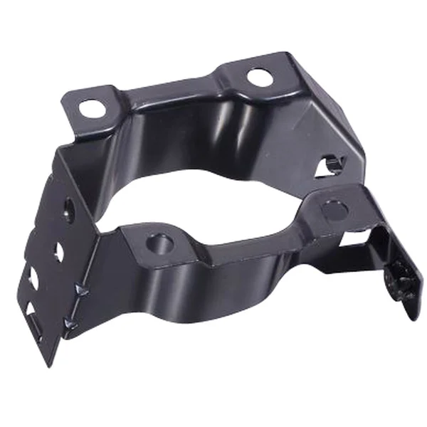
A contoured bracket with flanges in three directions has no good flat
The defining difficulty on this automotive bracket is that the flanges leave the contoured body in three different directions. That means there is no orientation where all the bends are visible, no single flat reference surface, and no way to inspect the finished part as a planar object. It also means the die must hold a contoured surface that resists being flattened, form a flange perpendicular to a curve rather than to a flat, and pierce a pattern held to +/-0.10 mm after all of it has happened.
In 2.0 mm HSLA that combination is at the workable edge. HSLA is chosen because it delivers the required strength at 2.0 mm rather than 3.0 mm, and that choice is what makes the forming forces high enough for the contour itself to become the limiting factor. We run these on 5-250 T mechanical presses with dedicated dies, first articles and batch samples checked on the CMM, holding flange height to +/-0.08 mm and the hole pattern to +/-0.10 mm with critical dimensions 100% gauged. What follows is about the sequence – what the die does in what order, and how each operation moves the dimensions that matter.
Station order is a decision about which dimension moves last
The working order for a bracket of this shape is blank and pierce first, contour next, flange forming in ascending order of severity, cut-off last. Each step has a reason tied to a dimension.
- Pierce before forming. A hole punched in a flat blank is positioned by the punch and the strip. The same hole punched after the body is contoured is positioned by a contoured, springy surface, and inherits every spring-back variation in that contour. Moving piercing early removes the contour from the hole position error budget entirely, and that one choice is worth more than any gauge upgrade downstream.
- Form flanges least severe to most severe, so the station holding final geometry is doing the hardest work.
- Cut off last. Cut-off is where the part is freed and can move, so nothing dimensional should follow it.
The corollary is the most common review finding: any dimension held to a tenth of a millimetre should be created in the first two stations. A feature created in station six inherits every forming variation ahead of it, and no downstream die refinement brings it back.
Flange height is a pressure problem, not a length problem
Flange height is dimensioned as a length on the print, so it is natural to treat it dimensionally. It is not. On a formed flange, height is produced by the pressure the die exerts over the bend and by how much material is allowed into the bend arc. It is a consequence of material displacement, which is why the same die can produce a flange 0.08 mm under on one part and 0.08 mm over on the next while every station is functioning within specification.
Three variables drive the variation, and each has a different remedy.
- Material thickness band. The largest contributor, and not under the die maker’s control. 2.0 mm HSLA ordered to a general tolerance can arrive anywhere from about 1.75 to 2.25 mm. A thicker blank forms a larger bend arc for the same punch penetration, which eats flange height. Across a 0.5 mm thickness band on one 90-degree bend at a 2.0 mm radius, the height shift is on the order of a third of that band – more than the whole tolerance.
- Bend radius variation in the die. Every bend edge is ground, and its radius changes as the die wears. A radius growing 0.1 mm adds material to the arc and reduces height by roughly 0.05 mm on one side. Over die life this is the difference between a die that is done and one that is not, which is why die life and flange tolerance are the same conversation.
- Spring-back variation with the incoming coil. HSLA from different heats has different yield-to-tensile ratios, so the same coil position in the same die does not give the same flange height coil after coil. That is why heat-number traceability travels with the first article.
The conclusion is uncomfortable but simple: flange height at +/-0.08 mm on 2.0 mm HSLA is only achievable if the thickness band is specified. Plus or minus 0.10 mm on nominal 2.0 mm is normal mill capability; plus or minus 0.05 mm requires a coil selection and costs more per part. Tightening the dimension further without tightening the band buys measurement noise, not capability.
Forming a flange off a contour is not the same as forming it off a flat
A flange bent off a flat has a clean, uniform neutral axis across its width. A flange bent off a contoured body does not, and this is the single most important difference between this part and a straight-flanged bracket.
The tooling answer is that the flange punch has to be profiled to follow the contour, with the nose ground to the same curve the body has and the relief at the ends opened out so material can draw in rather than being stretched. Where the flange is more than about 15 mm wide or the contour curvature tighter than roughly a 15 mm radius, this is a real profiling operation and it belongs in the tooling discussion, because a straight-punch attempt at this geometry produces a part that passes inspection and fails assembly.
The hole pattern and everything that happens to it on the way out
Holding a pattern to +/-0.10 mm across a contoured, flanged bracket means controlling four separate displacements, and only one of them is the punch.
- Punch position, within a few hundredths of a millimetre if the strip is located and the die is not worn. This is the easy part.
- Forming displacement. This is what actually moves the holes, and it is why the station order above is not a preference.
- Part movement on ejection. Once cut off, the part is free, and a formed part with three flanges is not symmetric. It sits differently on a fixture depending on which flange touches first, so the fixture has to locate it positively or the measurement shows variation that belongs to the fixture, not the part.
Material thickness band is the tolerance floor, and it is not a shop decision
The point most often misunderstood in bracket reviews: the achievable tolerance on a stamped and formed dimension is bounded below by the incoming material band, and no die technique removes that bound.
The arithmetic is direct. Suppose flange height is set by penetration of a fixed punch nose. The resulting height is a function of the bend arc, and the bend arc is a function of thickness. If thickness varies by plus or minus 0.10 mm on 2.0 mm nominal, the flange height varies by a fraction of that – call it 0.06 mm – purely from the incoming material, before any die wear, coil-to-coil spring-back variation or press temperature effect. The process is then at 0.06 mm of unavoidable variation against a 0.16 mm total band. That leaves very little room, and the honest conclusion is that the drawing and the purchase specification have to be designed together.
- State the thickness band explicitly as a requirement on incoming material, not as a note. Plus or minus 0.10 mm on 2.0 mm is normal mill capability for HSLA; plus or minus 0.05 mm needs coil selection and costs more per part.
- Do not specify a thickness tolerance tighter than the coating system preserves. A formed flange height is measured on material whose nominal thickness is a coating-under steel thickness. If the finish adds anything meaningful, the nominal must account for it.
- Classify dimensions. The two or three functional dimensions should be tight and everything else opened up. Every 0.1 mm given back on a non-functional dimension is directly available for the functional ones.
And one thing follows for the inspection plan: capability must be demonstrated across a run, not on a single first article. A part that measures within tolerance proves nothing about a variable driven by coil-to-coil variation. The first article should carry a dimensional report, and the process should run through at least a partial coil before the tolerance is confirmed as capable rather than merely met.
Questions worth settling before this die is cut
These are the questions on this geometry where the answer changes the tool rather than the paperwork, which is why they belong in writing before tooling starts.
- Are all functional holes pierced in the first two stations, before any forming station touches the part?
- Is the thickness band stated as an incoming material requirement, and is it consistent with the flange height tolerance?
- For each flange, is it bent off a flat segment or off a curve, and if off a curve, is the punch profiled to that curve?
- Are corner reliefs at the flange-to-contour transitions at least twice the flange height, and radii rather than square cuts?
- What is the bend radius at each flange base, and can the punch hold it at 2.0 mm HSLA without cracking the outer fibre?
- Is the strip positively located at every station, and is pitch error verified rather than assumed?
- Does the last station positively seat the part, given that a three-flange bracket rocks on a point ejector?
- Is stripper heel pressure specified, and does the stripper land on material that has already been pierced or on material about to be?
- Are non-functional dimensions opened up so the capability budget can go to the functional ones?
- Is the first article measured across a partial coil rather than on three consecutive parts from one position?
The stripper question is not trivial. On a progressive where flanges form at the same stations as the piercing, the stripper holds the sheet down while the flange forms, and it has to land somewhere that does not distort a dimension you care about. A stripper landing 5 mm from a critical flange changes the flange angle, and the change is repeatable and therefore invisible to anyone not looking for it.
Parts like this one sit under the Custom Metal Stamping Parts range, whose overview page gathers the tooling logic, finishing options and tolerance notes shared across the family.
Specifications
| Item | Progressive Die Stamped Formed Bracket for Automotive |
|---|---|
| Brand | AUNOV |
| Designing | Built to the drawing you supply – the die is planned around your critical features, so changes are priced before tooling is cut. |
| Tooling | Tooling is held under your part number, which keeps tooling cost transparent, and maintenance is tracked against the part number. |
| Samples | First-article samples ship with a dimensional report and material certificate, and any deviation is corrected at sample stage, Production starts only after your written sign-off. |
| Materials | HSLA steel, 2.0 mm; mill certificate and heat-number traceability supplied with the first article. |
| Surface finish | Plating, coating or polishing to suit the drawing; masking and laser marking available where needed. |
| Processing | progressive stamp – a formed bracket carrying flanges bent in three directions around a contoured body. |
| Equipment | Press shop with 5-250 T mechanical presses and dedicated dies; first articles and batch samples are checked on the CMM. |
| Tolerance | ±0.08 mm flange height; ±0.10 mm hole pattern; critical dimensions 100% gauged. |
| Delivery terms | FOB, CIF or DDP per Incoterms 2020; T/T with deposit; price breaks tied to annual volume. |
Related Products
Request a Quote for This Part
Send a drawing or sketch — get material advice, tooling cost and a per-piece price within 24 hours (working days).