
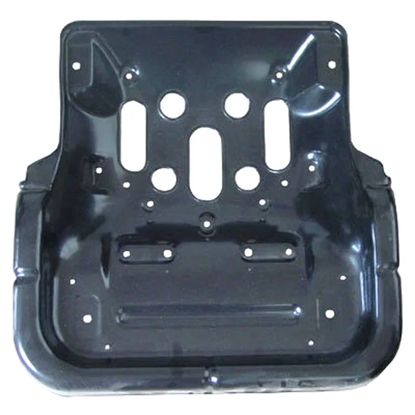
The datum moves when a flat blank becomes a drawn cup
This component is deep drawn in HSLA at 1.8 mm, and the most consequential decision in the process is where the datum lives before and after drawing. On the flat blank every dimension is measurable from the sheet plane. Once the blank becomes a shell wrapping the occupant-side structure, the sheet plane no longer exists as a single surface, and any dimension the drawing refers to the blank in has become a derived rather than a direct measurement.
The failure mode is quiet.
The way out is to declare the datum on the drawn feature rather than the trimmed edge. Where the part has a flange, that flange plane is the most stable datum available: it forms against a flat die face and does not spring back. A profile trim tolerance referenced to it will control what matters, which is the part’s position in its assembly. This is a drawing-review conversation that costs nothing before tooling.
- Flange as datum — the annular face formed against the die is the stiffest, most repeatable reference on a drawn shell.
- Avoid trim-referenced datums — a trimmed edge moves with the trim die’s own wear and with any draft in the shear.
- Axis definition — the draw axis should be established from the flange plane and one wall feature, not from two opposing walls, which can be unequal after drawing.
- Report on the shell — ask the inspection plan to report profile positions in the shell’s own frame, so a batch trend is readable.
Draw ratio decides whether 1.8 mm HSLA survives the process
Draw ratio — the ratio of the blank diameter to the die opening — is the number that decides whether this part draws at all, and it interacts with material strength in a way that is not linear. On 1.8 mm HSLA the wall experiences both stretching and bending through the draw, and the limiting factor is usually the tensile strain at the punch nose, where the material has to wrap the smallest radius while being restrained by the flange.
This part wraps the occupant-side structure, so the ratio is substantial — which is exactly why the operation is quoted as deep draw rather than shallow form. The question for us is whether it draws in one operation or needs a two-stage draw with an intermediate anneal. Single draw is cheaper per part and much cheaper in tooling. A two-stage route costs an anneal — at line speed a real capital and floor-space item — plus an extra press, but it recovers ductility that a single aggressive draw consumes. At low volume single draw is almost always right; at high volume the two-stage route often becomes cheaper per part once scrap and rework are counted.
Single draw is cheaper per part and much cheaper in tooling. A two-stage route costs an anneal — at line speed a real capital and floor-space item — plus an extra press, but it recovers ductility a single aggressive draw consumes. At low volume single draw is almost always right; at high volume the two-stage route often wins once scrap and rework are counted.
- Nose radius — the punch nose radius sets the minimum bend the wall sees. On 1.8 mm, keep it at four to five times thickness. A sharp nose on HSLA is the classic initiator of a corner crack that appears two weeks into production.
- Wall thinning — measure thinning at the punch nose at first article, not just wall length. A 10 % loss on 1.8 mm is 0.18 mm of material, which matters on a weld-through or structural flange.
- Flange wrinkling — a draw too shallow for its ratio wrinkles at the flange; too aggressive and it stretches the wall. The window between them is set by blank holder force, making it a first-article parameter rather than a fixed machine setting.
- Ears — a four-lobe blank develops earing at roughly 45° to the rolling direction; on a non-round part that reads as profile trim variation around the circumference. It is a material anisotropy problem, not a tooling problem.
Blank holder force is the process variable nobody can set by eye
So blank holder force belongs in the tooling record as a number with a tolerance, and the process is qualified on the production coil rather than a material certificate. Run first article on production material, adjust force in small increments, and record the setting at which nose thinning and flange wrinkle both go out of limits — that setting becomes the documented window — a band, not a point.
That is why blank holder force belongs in the tooling record as a number with a tolerance, and why the process is qualified on the actual production coil rather than on a material certificate. The practical technique we use is straightforward: run first article on the production material, adjust force in small increments, and record the setting at which wall thinning and flange wrinkle are both outside their limits. That setting then becomes the documented window, typically a band rather than a point.
Lubrication interacts with holder force more than most expect. A well-lubricated part needs less holder force for the same flow behaviour, lowering draw force and the risk of the blank tearing at die entry. Over-lubricating has its own cost: oil carries into the part, shows up at coating, and can interfere with welding or bonding downstream. Trimming lube is a real parameter in a stable draw.
There is a cost angle worth stating plainly. Narrowing the blank holder force window costs trial time at first article and robustness across a coil campaign; widening it costs scrap. Where a rejected shell means a scrapped occupant-side structure, the window is worth narrowing, and that price belongs in the quotation.
Profile trim tolerance is set by the draw, not by the trim die
A ±0.10 mm profile trim looks like a shearing tolerance, and it is tempting to assume a good trim die holds it. It does — relative to the blank it cuts. What it cannot do is recover positional variation the draw already introduced. If the drawn edge wanders 0.15 mm against the draw axis, a perfect trim die reproduces it faithfully.
So the trim tolerance splits into two terms: the trim die’s own cutting accuracy, and the incoming edge position from the draw. The first is easy to control — sharp punch, sharp die, correct clearance, rigid trim shoe. The second is where the effort belongs, and its tools are a well-supported draw die, a repeatable blank position at trim, and a locating scheme referencing the flange rather than the material.
- Trim clearance — on 1.8 mm, side clearance around 6–8% of thickness; below that the edge tears rather than shears and the burr grows faster than wear does.
- Trim support — the shell must be fully supported behind the trim line. An unsupported edge deflects under trim shear load and produces a profile that is accurate at the start of the cut and out of tolerance by the end.
- Draft in the shear — any draft in punch or die consumes part of the trim tolerance as angle rather than position. Keep shear faces parallel.
- Burr on a drawn edge — the drawn shell already carries a formed edge before trimming; the trim adds a sheared edge on top. Where a customer sees a “burr complaint” on a drawn part, check whether they are looking at the draw burr or the trim burr — they need different fixes.
Wall features at ±0.15 mm after drawing are a forming tolerance
The wall features called to ±0.15 mm are formed features, and that matters: one is governed by springback, by whether it forms in the draw or a later redraw, and by whether the tool was compensated for the springback it actually produces.
The common sequence is draw first, then form the wall features in a second operation on a smaller press. The features then form on a rigid, already-stiff shell rather than in the draw stroke, so the forming is repeatable. Doing it in the draw stroke is cheaper but couples every feature’s accuracy to the draw’s own variability.
A two-operation route needs two datums. The second operation must locate the part on its flange, and the locating features must not themselves be the toleranced wall features. With several wall features, nominate one as the locator, make it a tight tolerance, treat the rest as secondary. If every feature is nominal and none is nominated, the drawing is unmakeable and the first article will say so. Springback compensation follows the same discipline as bend angles: measure the achieved feature at first article, calculate the offset, record it in the die’s fabrication data. On HSLA at 1.8 mm that offset is large enough that ignoring it puts a wall feature outside ±0.15 mm on the first attempt.
Springback compensation for these features follows the same discipline used for bend angles: measure the achieved feature at first article, calculate the offset, and record it in the die’s fabrication data. On HSLA at 1.8 mm the offset is large enough that ignoring it puts a wall feature outside ±0.15 mm on the first try.
Two failure modes that arrive weeks after the part ships
Deep-drawn HSLA components have characteristic late failures, and both originate at the draw rather than in service.
The first is corner cracking at the punch nose. The wall stretches as it wraps the nose, and HSLA has limited ductility at that strain. The crack initiates at the outer fibre, is too small to see on a first article, and propagates with each thermal cycle. The part passes incoming inspection, passes assembly, then fails in service at a corner. Prevention is nose radius and draw ratio, both decided at flat-pattern stage — neither is recoverable later, because by then the geometry is committed.
The second is a dimensional shift from residual stress. Drawing leaves a non-symmetric residual distribution; cut the part free and it moves. The movement is small but not zero, and on a component with a ±0.10 mm profile trim it consumes a meaningful fraction of the band. Mitigations are balanced blankholding, consistent lubrication, and letting the part settle — some designs specify a rest period between draw and trim so the elastic component completes before the cut fixes the geometry.
- Corrosion initiation at a formed corner — a sharp nose radius leaves a work-hardened corner with reduced coating adhesion. Radius and plating coverage are linked decisions.
- Weld distortion — if a sub-assembly is welded downstream, the weld shrinkage can move the very features this drawing calls out. Flag the weld sequence at quotation so the datum strategy accounts for it.
- Handling damage — a thin-walled drawn shell is easily dented in handling. The part may be dimensionally perfect on the CMM and out of tolerance on the line, which looks like a measurement dispute and is not one.
Both failures share a lesson worth stating at design review: on a drawn HSLA component the process determines tolerance capability far more than the machining does, and the drawing must be written accordingly.
From 5–250 T presses to a released part number
This component runs as a deep draw on presses in the 5–250 T range, with first articles and batch samples on the CMM.
- DFM before quotation — draw ratio, nose radius, corner relief and blank shape are reviewed against the print, and changes that reduce development risk come back with the quotation, not after the die is cut.
- Tooling under the part number — the draw die, trim die and forming die are logged against this part, so a die can be re-cut from the original design data and so maintenance history travels with the number.
- Process parameters recorded — blank holder force, punch speed, lube quantity and springback compensation go into the die record, not a shift note.
- First article before production — production starts only after written sign-off, with nose thinning, flange condition and wall features all measured, not just the outline.
- Batch sampling tied to the signed article — later batches are gauged back to the signed sample, so the reference never drifts to the most recent lot.
On the commercial side, price breaks tied to annual volume and Incoterms 2020 delivery are quoted, with tooling a separate refundable line. Sample sign-off before production is not formality: on a deep draw the first article is where the process window is discovered, and producing before that window is known means finding it mid-batch with every part suspect.
Custom Metal Stamping Parts is the parent range for parts like this one; the overview page gathers the tooling logic, finishing options and tolerance notes that apply across the family.
Specifications
| Item | Deep Drawn Automotive Seat Stamping Component |
|---|---|
| Brand | AUNOV |
| Designing | Made to your 2D/3D drawings (PDF, DWG, STEP, IGS) – DFM notes come back with the quotation, and revisions are re-quoted once rather than silently absorbed. |
| Tooling | Tooling is held under your part number, so a die can be re-cut from the original design data, and lead time is measured from tooling start. |
| Samples | Pre-production samples come with a full inspection report, and any deviation is corrected at sample stage, Production starts only after your written sign-off. |
| Materials | HSLA steel, 1.8 mm; mill certificate and heat-number traceability supplied with the first article. |
| Surface finish | Finish selected from the drawing: plating, coating, anodising or passivation; the agreed finish travels with the part number. |
| Processing | deep draw – a deep-drawn seat stamping that wraps the occupant-side structure. |
| Equipment | 5-250 T presses running progressive and compound dies; first articles and batch samples are checked on the CMM. |
| Tolerance | ±0.10 mm profile trim; ±0.15 mm wall features; critical dimensions 100% gauged. |
| Delivery terms | FOB, CIF or DDP per Incoterms 2020; T/T with deposit; price breaks tied to annual volume. |
Related Products
Request a Quote for This Part
Send a drawing or sketch — get material advice, tooling cost and a per-piece price within 24 hours (working days).