
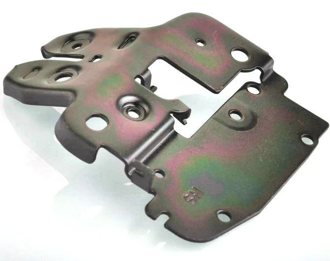
A dense locating-hole pattern turns die pitch into the tolerance stack
A chassis mounting bracket rarely fails because its material choice was wrong. It fails because six holes that each sit inside ±0.10 mm do not land in the same relationship to each other after the bracket has been through a five-station progressive die. Position tolerance on a drawing is normally read as a per-feature limit, and it is measured that way on the CMM. What actually reaches the vehicle floor is the cumulative error across the pattern: the pitch error of the pierce stations, the walk of the strip as it indexes, and the movement of the material itself while the flange is being formed. On this bracket the figure that matters is the pattern’s own positional deviation relative to the datum, not the number printed beside each hole.
The arithmetic is unforgiving. A progressive die carries pitch error because the strip is fed by a roll or pin feed with finite accuracy; a typical station-to-station pitch variation of ±0.03 mm does not stay a single error. Add a piercing punch on a holder with a little float, add a forming station that pulls material sideways as the flange wraps, and a 60 mm span between the outermost locating holes inherits several times the single-hole figure. This is why we quote the pitch and the pattern span, not just the hole figure.
- Pattern span tolerance — govern the distance between the two outermost locating holes as a separate dimension, referenced to the same datum as the individual holes. This is the dimension that controls assembly.
- Pierce station pitch — confirm against your machine the indexing accuracy the die can actually hold, not the accuracy the feed unit advertises.
- Datum choice — a datum established on a formed flange will move as the flange relaxes; a datum on the flat pierced web is far more stable through the whole process.
- Inspection mode — if critical dimensions are 100% gauged, decide now whether that means 100% CMM or 100% on a dedicated go/no-go gauge; the two have very different cost profiles.
Pierce-to-form datum drift is what actually moves a ±0.10 mm hole
Here is the mechanism that catches people out. The hole is pierced in station two, while the blank is still flat. The flange is formed in station four, and the blank is still attached to the strip at that point. Then the part is cut free. Anything that happened between piercing and cut-free — thermal growth of the die, springback of the formed flange, the draw-in of material as the flange wraps — moves the finished hole relative to the flange that a downstream assembly datum is taken from.
For a 2.5 mm HSLA bracket the dominant term is not thermal drift, it is material draw-in. When a 90° flange forms over a punch with an 8 mm inside radius, material is pulled from the web into the bend. That shortens the flat, expands the flange, and it does it asymmetrically if the two sides of the bracket are not symmetric. If the assembly datum is a formed boss rather than the pierced web, the designer has accidentally written a tolerance that includes the bend deduction and its variation.
The practical move is to order operations so that critical locating holes are pierced after the largest forming operation wherever the design allows it. If that is impossible, make the forming operation’s variation small and repeatable: tight shut-off, a well-supported die shoe, and a formed radius that is not being used as a locating feature.
Thermal growth is cheap to fix and embarrassing to ignore. A 250 T mechanical press running a continuous die can put 3–6 °C into the die set over the first hour of a shift — on a 400 mm die line, roughly 20–25 µm of growth. The first article is measured cold and the four-hundredth warm; at ±0.10 mm, that is a fifth of the budget gone to something no gauge can see.
On 2.5 mm HSLA, burr direction decides whether the fastener seats
Fastener seating is a burr problem before it is a tolerance problem. A pierced hole in 2.5 mm sheet carries a burr whose height is set by punch-to-die clearance and by how sharp the punch edge is. On HSLA at this thickness the burr typically stands 0.05–0.12 mm proud, and it sits on one side of the hole — determined by the piercing direction relative to the part’s orientation in the assembly.
That side matters. A M12 fastener torqued into a hole with a 0.10 mm burr on the bearing face sits high by roughly the burr height divided by the thread pitch — a meaningful fraction of a turn at a 1.75 mm pitch. The bracket can measure perfectly on the CMM and still fail the torque-to-seat check. We plan piercing direction from the assembly drawing, not the flat pattern, so the burr lands where the fastener head will not see it.
- Clearance — punch-to-die side clearance around 5–8% of thickness is the starting window on HSLA. Too little and the burr becomes a tear; too much and the hole wall carries a rolled, work-hardened layer.
- Punch condition — burr height grows once the punch edge breaks. On a high-volume bracket, punch regrind interval belongs in the maintenance plan, not left to feel.
- Break edge — a 0.3–0.5 mm break on the punch shoulder is cheap and controls the rollover at the hole entry.
- Deburring route — a light vibratory or tumble deburr removes the burr; a heavy one rounds the hole entry and eats into your hole-position callout, because the entry lip no longer defines the true edge.
The reverse question matters too. Is the burr acceptable to leave in? For a painted bracket that is then bolted, yes, and skipping deburring is a real saving. For a hole taking a dowel or press-fit stud, no. Tell us which holes are functional and which assembly-only — the two groups want opposite burr treatments.
Flange forming: the shut-off height nobody puts on the quotation
The drawing says ±0.15 mm on the formed flanges. What it does not say is the shut-off height — the distance the die must close past the theoretical part height to actually deform the material to nominal. Get that number wrong and the flange is either undersized or the die is crushing the web. Both are scrap, and both are visible only after the part is cut free, which is the most expensive place to discover them.
On a 2.5 mm HSLA bracket formed over a punch with an 8 mm inside radius and a 12° bend, bend deduction is roughly 1.7 mm and bend allowance lands around 3.1 mm. The flat pattern must be built from those numbers, and the shut-off set from the same numbers. Change the inside radius for cosmetic reasons without re-deriving the flat, and the finished flange height drifts by several tenths of a millimetre while every pierce stays perfectly in position.
There is a cost decision here too. Tight shut-off produces accurate flange heights but raises die wear and press tonnage demand. Loose shut-off is gentler on the tool and gives a flange height that wanders band to band. On a bracket whose flange is structural bending flange carrying vehicle load, we take the tight shut-off and pay for punch maintenance. On a bracket whose flange only locates a trim panel, a looser shut-off inside ±0.15 mm is the sensible trade.
- Bend allowance sensitivity — every 0.5 mm added to the inside radius moves the flat pattern by a similar magnitude. Radius is not a free styling choice.
- Springback — HSLA at 2.5 mm springs back measurably more than mild steel. If the flange angle is functional, over-bending by an amount established at first article is cheaper than a re-tool.
- Flange length tolerance — driven by shut-off and thickness variation together; both must be inside budget or the flange never holds its band.
- Support — a long cantilever flange formed unsupported will twist; a bolster pad under the free end costs almost nothing and removes the twist.
The wear budget across 300 ksh, and where it lands on the bracket
A progressive die is a consumable with a finite life, and on this bracket wear shows up in three places with different consequences. Pierce punches and their die buttons wear on the punch flank and the hole wall. Forming punches wear on the radius and the shoulder. Cutting edges wear on the corner. Knowing which is actually failing tells you whether the tolerance problem has a maintenance answer or a design answer.
Rough planning figure: a carbide-lined pierce station handling 2.5 mm HSLA runs several hundred thousand strokes before hole position drifts enough to matter; hardened tool steel is shorter-lived. Published life figures assume clean, well-lubricated steel and a sharp edge. Dirty coil or edge-built material cuts those numbers by a large factor, and coil cleanliness is the variable that most often destroys the assumption.
The tolerance consequence is not uniform. Piercing wear shows up as hole position growth and a rising burr; the fix is regrind, which does not move the pattern permanently. Forming wear shows up as a flange height that slowly drops and a corner radius that grows; that one is cumulative and eventually needs die repair rather than a polish. Cutting-edge wear shows up as a corner that fails the ±0.15 mm flange callout. Any of the three can be tracked by comparing first article against current on a fixed gauge, which is cheaper than waiting for a customer complaint.
Design the gauge so the wear-sensitive features are the ones you measure. A gauge checking overall length on a bracket whose real risk is hole pitch measures the wrong thing well.
Why ±0.15 mm on a flange and ±0.10 mm on a hole are not the same problem
It is tempting to treat both numbers as a single “precision” claim and to argue the tolerance down uniformly when a customer pushes back on cost. They are not interchangeable, and the cheapest tolerance reduction is almost never uniform.
- Hole position is governed by the pierce station: punch alignment, feed accuracy, wear state, and the datum you chose. Improving it means better feeds, tighter die construction, or moving the operation.
- Formed flange is governed by shut-off, thickness variation and springback. Improving it means die-surface work and incoming material control, not alignment.
- Pattern span is governed by all three, and is the one that actually causes assembly problems. It deserves its own callout even when each individual hole passes.
This split also decides where inspection effort is worth spending. If the field failure is a bolt not lining up, gauge the pattern span and the datum. If it is a flange fouling a neighbour, gauge the flange angle and its springback. Running a CMM programme that checks every dimension equally is how a 100% gauging promise turns into a cost nobody wants to pay for.
Tell us at quotation stage which failure mode you are designing against. On this bracket the common answer is “the bolt pattern”, and that answer puts the effort into the pierce stations and the pattern callout rather than the cosmetic accuracy of the flange corners.
Running 100% gauging on critical features without choking the cell
Stating that critical dimensions are 100% gauged is a commitment that shapes the whole production plan, so it is worth planning rather than discovering. Three routes exist and they scale very differently with volume.
- Offline CMM, sampled — first article and a periodic sample. Cheapest, weakest guarantee. Acceptable when the customer controls incoming inspection anyway.
- In-line go/no-go gauging — fixed attribute gauges at the press plus periodic CMM correlation. Fast enough for volume, and it catches drift at the station rather than at the end of the batch.
- In-die sensing — sensors in the die that watch the process window rather than the part. Excellent for catching early drift; does not replace part inspection on its own.
The part often missed is correlation. A go/no-go gauge that has drifted is worse than no gauge, because it gives false confidence. Whatever route you choose, the gauge needs a calibration interval and a periodic tie-back to the CMM, written down at sample-approval stage.
For this bracket we normally recommend in-line attribute gauging on the hole pattern, with CMM verification on first article and at a fixed periodic rate. That catches the two failure modes that matter — a shifted pattern and a growing burr — without turning the press cell into a metrology laboratory.
Custom Metal Stamping Parts is the range this part sits under; the overview page pulls together the tooling logic, finishing options and tolerance notes that apply across the family.
Specifications
| Item | Automotive Chassis Stamped Mounting Bracket |
|---|---|
| Brand | AUNOV |
| Designing | Built to the drawing you supply – the die is planned around your critical features, so changes are priced before tooling is cut. |
| Tooling | Die, fixture and gauge work stays in our own toolroom, so the die charge is a separate, refundable quotation line, and lead time is measured from tooling start. |
| Samples | Samples are issued for approval before the run, and any deviation is corrected at sample stage, The signed sample is retained for future reorders. |
| Materials | HSLA steel, 2.5 mm; mill certificate and heat-number traceability supplied with the first article. |
| Surface finish | Plating, powder coating, anodising or polishing, per the print; masking and laser marking available where needed. |
| Processing | progressive stamp – a chassis mounting bracket pierced with a dense locating-hole pattern and heavily formed flanges. |
| Equipment | Mechanical presses 5-250 T with progressive dies; first articles and batch samples are checked on the CMM. |
| Tolerance | ±0.10 mm hole position; ±0.15 mm formed flanges; critical dimensions 100% gauged. |
| Delivery terms | FOB with DDP offered for EU and US addresses; payment T/T or L/C, freight quoted to destination. |
Related Products
Request a Quote for This Part
Send a drawing or sketch — get material advice, tooling cost and a per-piece price within 24 hours (working days).