
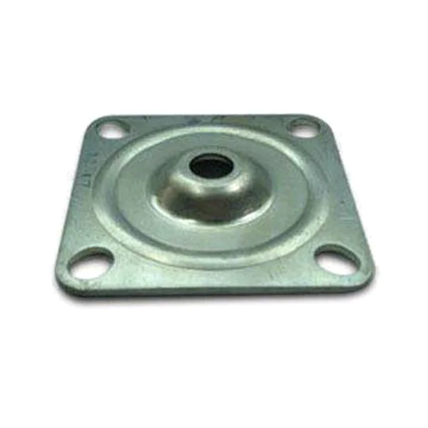
A full perimeter flange on 1.0 mm is a drawbead problem wearing a flange
This cover is deep drawn with a full perimeter flange in SPCC at 1.0 mm, and the flange is called to ±0.10 mm on width. It looks like a simple flange because it runs all the way around, but a continuous flange is harder than a partial one for a reason that is easy to miss: there is nowhere for the material to go.
In practice that shows up as a flange that is nominally correct and locally wrong. The flange is widest where material is drawn in freely and narrowest at the corners where it is resisted, and because the corners are also where the draw ratio is highest, they are doubly disadvantaged.
- Corner flow — the flange width at a corner depends on how much material is drawn across the diagonal. Square corners on a drawn cover need generous corner radii precisely because a sharp corner cannot accept flange material.
- Flange width variation — measure at the mid-side and at the corner, not just at one location. A cover that passes at mid-side and fails at the corner will pass incoming inspection and fail assembly.
- Draw ratio — 1.0 mm SPCC draws easily compared with the HSLA parts in this range, so the flow window is wider, but continuous flanges still need the corners designed rather than assumed.
- Flatness after trim — a continuous flange is the part’s stiffening feature. If it is not flat, the cover will not seat, and a flange width tolerance will not tell you why.
The practical drawing recommendation is to specify flange width at both the mid-side and the corner, with the corner callout as the controlling one. That single change turns an unmakeable requirement into one where the corner has to be designed and where the die has a defined target.
Zinc plating thickness is a tolerance decision on a 1.0 mm cover
The finish here is iridescent zinc, and the flange is called to ±0.10 mm. Those two facts interact more than they appear to. A zinc electroplate at 8–12 µm adds that much to every surface; on a flange width measured across two opposed faces, the plating consumes 16–24 µm of the dimension.
Iridescent zinc is a chromate conversion over a zinc deposit, and the conversion layer itself is very thin — so the dimensional cost is essentially the zinc thickness. That makes it one of the cheaper finishes dimensionally, which is worth saying explicitly against nickel or a build-up copper process.
- Dimension to the plated condition — the drawing dimension should be the finished dimension, and the die should punch undersize by the expected coating build. On a flange width that means 16–24 µm of deliberate undersize at 8–12 µm per face.
- Masking — mask any face used as a seating or datum surface. A flange that seats on a plated face has a coating thickness between it and the mating part, and that thickness varies with the bath.
- Edge build — a sheared edge on 1.0 mm is thin and takes coating unevenly. The flange edge is where the visible corrosion question starts, not the flat faces.
- Plating before or after assembly — if the cover is plated loose, the flange can be masked cleanly. If it must be plated assembled, masking is harder and dimensional control is worse.
There is a second-order effect worth raising on a drawn cover. The flange is a stress-relief feature — it exists so the cover can be drawn without tearing. Plating a drawn flange adds a rigid, brittle layer to a region that is deliberately allowed to flex slightly as the cover seats.
±0.15 mm on the outer square is really four separate corners
The outer square is called to ±0.15 mm, and the temptation is to treat that as a single dimension. It is four. A square has four corners, four sides and a squareness question, and each of those can drift independently of the others.
There is also a form-versus-orientation distinction that matters more than the tolerance number itself. Out-of-square on a square cover means the four sides are not all the same length. That is a form error, and form errors on drawn parts come from the draw, not from the trim.
- Define the datum — squareness needs two adjacent sides or three points. A single side as datum leaves squareness undefined, and the drawing review should catch that before the die is cut.
- Corner radius is part of the tolerance — on a drawn cover the corners carry a radius whether or not the drawing says so. The radius is what makes the corner flow possible, and its variation is part of what the outer square tolerance has to absorb.
- Twist after cutting — releasing a drawn cover from the blank ring redistributes stress, and a cover with a continuous flange can twist slightly. That changes squareness without changing any side length.
- Flatness and squareness interact — a cover that is not flat will not read square under a squareness fixture. Check flatness first, or the squareness reading is meaningless.
The practical inspection answer is to measure squareness as a form deviation and report it separately from the side lengths. A cover that measures 120.00 on all four sides within ±0.05 but is 0.30 mm out of square is a very different part from one whose sides vary — and the two fail in different ways in assembly.
Deep draw plus trim: the second operation inherits the first one’s errors
This part is quoted as deep draw plus trim, and that two-operation route is where the tolerance story lives. In the draw, the blank becomes a cup with a flange. In the trim, the flange is cut back to its final width and the profile is freed.
The error budget for the flange width therefore has three contributors, and they are not equally controllable. Trim die accuracy is the easiest: a sharp punch, sharp die, correct clearance, a rigid trim shoe. Draw flange flatness is next: it depends on the flow being symmetric.
- Trim support — on 1.0 mm a flangelessupported cut will deflect under shear load and produce a flange that is accurate at the start of the cut and out by the end. Support the full flange behind the trim line.
- Trim clearance — around 5–7 % of thickness per side on 1.0 mm SPCC. Below that the edge tears; above it the cut edge rounds and the flange edge loses definition.
- Trim direction — cutting inward from the outer edge toward the material that is still attached keeps the part supported longer than cutting the reverse way round.
- Rest period — some covers specify a controlled interval between draw and trim so that elastic stress release completes before the geometry is fixed. On a cover with a continuous flange this is cheap and worth doing.
Where the flange is a sealing face or a seating face, the trim burr direction becomes a functional issue rather than a cosmetic one, and the trim should be oriented so the burr falls away from the sealing surface. That is a free decision at die design stage and an expensive one to change later.
A drawn cover traps stress, and the trap opens up in service
Drawn covers fail in ways that have nothing to do with the dimensions on the print, and it is worth being concrete about them because none of them are visible at incoming inspection.
The first is flange cracking from residual stress. Drawing leaves the cover with a stress distribution that is not symmetric about the flange root.
The second is coating adhesion failure at the flange root, for the same reason. A formed radius on drawn work is work-hardened and has lower surface energy than the flat faces, so a zinc coating there is thinner and less well bonded. On an iridescent zinc finish this shows as a dull, thin area at the flange root which becomes a corrosion site first.
- Stress relief between operations — where a cover is formed after drawing, an intermediate stress relief or a generous radius at the flange root prevents most of this class of failure.
- Handling — a thin drawn cover is easy to dent, and a dented cover is dimensionally correct and functionally wrong. This is a packaging question that gets misdiagnosed as a dimensional dispute.
- Assembly loads — if the cover is screwed down, the load path matters more than the flange width tolerance. A fastener pattern that loads the flange root directly will find any stress-related weakness.
- Plating rack marks — a plated drawn cover can pick up contact marks where it sits in the plating tank. On a visible face this is an appearance issue, and on a sealing face it can be a leak path.
The engineering conclusion is that on this cover the flange is simultaneously a tolerance feature, a sealing feature and a stress concentrator, and those three roles are in tension. That is worth stating at the design review, because it is much cheaper to change the flange geometry on a drawing than to change it on a die.
Corner radius on a square cover is a flow decision, not a styling choice
On a square cover the corner radius determines whether the flange can be formed at all. A sharp or small-radius corner cannot accept flange material, because there is no room for the material to travel into.
Because the outer square is called to ±0.15 mm, the corner region is where that tolerance is most likely to be consumed. The relationship is direct: a tight corner resists flow, flow resistance means the flange does not form properly there, and a poorly formed corner is both a width error and a stress concentration.
- Radius sizing — set the inside corner radius from the flange width, not the other way round. A flange that is 8 mm wide needs a corner radius that can physically be filled by material travelling that distance.
- Corner trimming — the trim punch has to negotiate the formed corner at an angle. Where the corner radius is small the trim punch loads unevenly and the corner of the flange ends up out of tolerance even when the sides are fine.
- Blank shape — a square blank with generous corner radii draws more predictably than one cut to the sharp outline. The blank is not visible on the finished part, so this is a free improvement.
- Report corners separately — put the corner dimension on the inspection report as its own line. A cover that passes on all four sides and fails at all four corners has told you nothing about its real condition if the report only shows side lengths.
A useful test at first article is to lay the trimmed cover on a flat plate and check for rocking at the corners. Rocking is a form error the side dimensions will not reveal, and on a cover that has to seal flat it is the first thing a customer notices.
Drawing, trimming and plating: the handover risk on a 1.0 mm cover
This cover runs through deep draw, trim and then iridescent zinc plating, checked on a climate-controlled inspection floor with CNC turning centres available for secondary work. Three process owners, three sets of dimensional conventions, and on a part this thin the handovers are where the risk sits.
- Draw — flow established, flange formed, corners developed. First article assessed for flow marks, corner condition and flange flatness before anything is cut free.
- Trim — flange width and outer square fixed. The trim is the last chance to correct anything, because after it the geometry is fixed by the cut.
- Plating — features dimensioned for the post-plate condition, with masking wherever a face seats or gauges.
The convention that prevents most arguments is simple: every inspection report states whether it is a bare-steel or a post-plate measurement, in the same datum and the same feature set.
On the commercial side, tooling here is held under the part number with ownership confirmed on the quotation, so a die can be re-cut from the original design data. Delivery is quoted FOB, CIF or DDP per Incoterms with payment by T/T or L/C.
The honest summary on this part is that 1.0 mm SPCC is a forgiving material to draw and a difficult one to finish. The draw will almost always work; the flange width and the outer square are what go wrong, and both are decided by flow and by the trim that follows it.
Drawing a cover like this is a chain of decisions — draw ratio, wall thinning, radii and trim. Our deep drawn covers design guide works through each of them with worked numbers.
Specifications
| Item | Deep Drawn Square Cover with Flanged Rim Zinc Plated |
|---|---|
| Brand | AUNOV |
| Designing | Quoted from your print, not a catalogue – the die is planned around your critical features, and the approved print governs every later batch. |
| Tooling | Tooling is held under your part number, which keeps tooling cost transparent, with ownership confirmed on the quotation. |
| Samples | Pre-production samples come with a full inspection report, so the deep drawn square cover is proven before volume production, The signed sample is retained for future reorders. |
| Materials | SPCC cold-rolled steel, 1.0 mm; mill certificate and heat-number traceability supplied with the first article. |
| Surface finish | zinc plating, iridescent; alternatives quoted against the drawing. |
| Processing | deep draw + trim – a square cover drawn with a full perimeter flange. |
| Equipment | Mechanical presses 5-250 T with progressive dies, backed by CNC turning centres and a climate-controlled inspection room. |
| Tolerance | ±0.10 mm flange width; ±0.15 mm outer square; critical dimensions 100% gauged. |
| Delivery terms | FOB, CIF or DDP per Incoterms – payment by T/T or L/C, with shipping quoted door-to-door. |
Related Products
Request a Quote for This Part
Send a drawing or sketch — get material advice, tooling cost and a per-piece price within 24 hours (working days).