
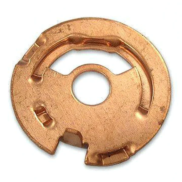
A tooth ring at ±0.05 mm is a pitch problem, not a size problem
This backing plate carries a tooth ring called to ±0.05 mm and a centre bore called to ±0.05 mm, and both numbers are about pattern rather than size. On a tooth ring the dimension that governs is pitch — tooth to tooth around the circumference — and pitch error accumulates.
This is the same accumulation mechanism that governs any multi-feature pattern, but on a closed ring it has nowhere to hide. On a linear strip of slots the error runs off the end and is notional; on a ring it closes back on itself, so accumulated error becomes a positional error at one specific tooth.
- Pitch callout — dimension cumulative pitch over a defined arc rather than adjacent teeth individually. Cumulative pitch is what a CMM measures repeatably and what actually controls the assembly.
- Runout — total indicator reading across the ring face relative to the bore, usually dominated by blank flatness rather than by the teeth.
- Wear direction — cutting-edge wear on the outer diameter shows as the ring growing or shrinking. Pitch error comes from feed accuracy and thermal growth, not from edge wear.
- Compiled error budget — at ±0.05 mm on 1.5 mm, blank flatness, thermal growth, feed pitch and punch wear each need a line item, added together rather than assessed one at a time.
Plating after stamping changes the process order, not just the finish
The finish here is bright copper plating, applied after the progressive stamp. That ordering is the central process decision, because copper plating is a soft, ductile, adherent coating that needs a clean, grease-free steel surface — and a stamped part carries exactly what plating does not want: punching oil, forming lubricant, and a shear edge that has to be broken before the coating will bridge.
Plating thickness also consumes dimensional budget directly, on a part whose features are called to ±0.05 mm. Copper electroplate at 10–20 µm adds that much per surface; on a bore that is 20–40 µm of diameter. A nominal bore punched to the drawing dimension comes out undersize after plating, and if it carries a shaft or a pilot that is a functional problem rather than a cosmetic one.
The resolution is to punch features undersize by the nominal plating thickness and dimension the drawing to the finished, plated condition. That requires the plating specification to be fixed before the die is cut. If the thickness is still being discussed at die design stage, somebody will design to the bare-steel dimension and the mismatch surfaces at the plating line, where it is expensive to correct.
- Undersize the bore — by twice the nominal plating thickness on diameter, since the coating builds on both walls. Confirm whether the bore is plated as-punched or finished first.
- Deburr before plating — a rolled edge from a torn punch does not plate evenly and can peel. A uniform light deburr is mandatory on any plated edge.
- Degreasing — punching and forming lubes are tenacious. The plating line needs a washed surface and a check that parts have been washed after deburr, not merely run through it.
- Masking — mask any datum face that must stay at bare-steel dimension, and any surface that will later contact the friction facing.
Appearance is a separate copper question. Bright copper is judged partly on the absence of haze and burn at high-current-density areas, and both follow from current distribution. A stamped part with a formed flange does not plate with the same distribution as a flat coupon, so the tank setup must be developed for this geometry rather than assumed from a standard cycle.
Copper on a stamped edge is a corrosion question before it is a look question
Bright copper is often specified where the real requirement is corrosion resistance with good appearance rather than conductivity. On this plate the environment is a friction facing, which brings its own chemistry: copper in a friction pair transfers to the facing material, and copper transfer onto a friction lining is a well-known cause of lining wear and glazing.
That creates a tension worth surfacing early. The drawing calls for copper; the assembly may see a friction pair that bare steel or zinc would serve better. Neither party is wrong — the copper may be there for thermal conductivity, for a repair surface, or because it is the historical specification.
- Adhesion — thin copper has poor adhesion on steel without a bonding treatment underneath. Ask which system is specified, because single-layer bright copper on a stamping is normally a build-up process rather than a single flash.
- Hydrogen embrittlement — acid copper baths charge hydrogen into high-strength steel. On HSLA and on any spring-energised part, baking within a defined window after plating is a specification requirement, not an optional extra.
- Edge protection — copper is noble and corrodes preferentially where it is thin. The sheared edge of a 1.5 mm stamping is the thinnest coated region on the part and therefore defines its salt-spray life.
- Mask the datum — mask the bore and any datum face before plating, or dimension the post-plate condition and re-gauge to it.
The practical test is simple: put the part in a salt-spray chamber and look at the sheared edge first. It fails before anything else does, on almost every copper-plated stamping, and it fails because the coating is thinnest there rather than because the bath was wrong.
Running clearance decides whether the tooth ring survives the programme
A tooth ring is cut by a punch and die that run against each other for the whole production run, and clearance decides whether the teeth come out crisp or ragged. On 1.5 mm steel the normal window is around 6–8 % of thickness per side, or 0.09–0.12 mm.
Teeth are more sensitive than ordinary holes because of aspect ratio. A tooth is a narrow land, often only a few millimetres wide, cut by punches slender enough to fit the pitch. Slender punches flex more under load and concentrate wear on the cutting edge in a way a large hole wall does not.
- Carbide for the long run — a carbide insert on the ring station holds its edge far longer than tool steel, and on this part that is a tolerance-life question rather than a throughput question.
- Punch edge condition — check tooth flank quality, not just burr height, at each regrind interval. The flank is what the friction facing actually reads.
- Break the shear edge — a 0.25–0.4 mm break on 1.5 mm sheet controls rollover and gives the copper something to bridge onto.
- Gauge tooth-to-tooth — a fixed gauge on three or four specified teeth catches flank wear months earlier than a diameter measurement will.
The cost-versus-life decision here is worth making explicitly. A tool-steel station might hold tolerance for 150 000 strokes where carbide reaches 800 000. Over several hundred thousand parts the carbide insert is not the expensive option; over a short run of 20 000 it is not worth the insert cost. The answer depends on annual volume, which is exactly why the volume break is asked at quotation.
Bore concentricity to the ring is a sequencing decision
The centre bore is called to ±0.05 mm, as is the tooth ring. What is usually not called out is their concentricity — and concentricity is what the friction facing cares about. A nominal bore and a nominal ring offset from each other by 0.2 mm produce a facing that runs out, so the friction characteristic varies as the disc rotates.
Concentricity is controlled by sequencing: cut the bore and the ring in the same station, or close enough together that the pitch error between them is negligible. Bore at station two and ring at station eight puts six indices of pitch error into the concentricity, which on this part is likely to exceed the whole tooth ring tolerance.
- Same-station cutting — a combined tool cutting bore and outer profile in one hit guarantees concentricity mechanically. Strongest and most economical answer where the geometry allows.
- Adjacent stations — if the ring and bore cannot share a station, keep them adjacent so only one pitch error accumulates.
- Distortion — if the ring is cut before the blank has relaxed, the flatness from earlier forming stations is still present and the ring follows it. Let the part settle before the finish cut where the tolerance demands it.
- Inspection method — a CMM can report bore and ring in one setup and compute concentricity directly. Requiring that single-setup measurement is worth more than tightening either tolerance.
The cost of getting this right on the drawing is close to zero, because it is an operation-sequencing choice made before the die is laid out. Getting it wrong is a die modification, and on a part with a tooth ring that means a new station insert at best.
What the friction facing needs from this plate, independent of tolerances
The functional description mentions a tooth ring and a central bore for friction facing retention, which means the mechanical route: the facing is bonded to the plate and the teeth retain the bonded layer. That mechanism sets requirements that have nothing to do with the dimensional tolerances, and they are the ones that decide whether the part works.
Surface condition is the dominant variable. Adhesive bonding to steel depends on surface energy, and stamping oils, forming residue and a copper plating are all poor bonding surfaces. Where the facing is bonded rather than mechanically retained, the copper sits in direct tension with the adhesive requirement — a real engineering conflict that has to be resolved by specification rather than by hope.
- Surface roughness — the tooth ring gives mechanical keying; the plate face between teeth gives the adhesive its bond. Consistent as-stamped roughness beats an inconsistent polished one.
- Cleanliness — a defined cleanliness level and packaging standard matter more than the coating itself on a bonded facing. Specify what the plate must look like arriving at the bonding cell.
- Flatness — a plate that is not flat will not bond uniformly, and the facing lifts at the high spot first. The ring is flat; the annulus between bore and ring may not be.
- Dimensional stability through bonding — heat from curing can move a thin stamped plate, and if the plate is held by the bore during that process the distortion shows at the bore.
The conclusion is that the tooth ring tolerance and the copper specification must be reviewed together, and that cleaning and packaging between plating and bonding is a controlled process rather than a handling step.
From progressive stamp to plated part, and the handover risk between them
This part runs as a progressive stamp with in-press forming and piercing, with secondary work on CNC turning centres, on presses in the 5–250 T range. The route has three process owners, and on a part like this the risk sits at the handovers rather than inside any one of them.
- Stamping — tooth ring, bore and profile cut in the die, with the concentricity decision made at layout stage. First articles and batch samples checked on the CMM in bare-steel coordinates.
- Deburr and clean — a light, uniform edge break to a defined cleanliness level. This is the step most often left implicit, and the one plating and bonding both depend on.
- Plating — bright copper on features dimensioned for the post-plate condition, with masking where a datum stays bare and baking where hydrogen embrittlement requires it.
The dimensional convention across those three steps is the thing to insist on at quotation. A CMM report taken on bare steel and one taken after plating are not comparable unless both reference the same datum and feature set.
Commercially, the die charge is a separate refundable line with tooling held under the part number, so a die can be re-cut from the original design data and maintenance is tracked against the number.
Custom Metal Stamping Parts is the parent range for parts like this one; the overview page gathers the tooling logic, finishing options and tolerance notes that apply across the family.
Specifications
| Item | Copper Coated Clutch Backing Plate Stamping |
|---|---|
| Brand | AUNOV |
| Designing | Quoted from your print, not a catalogue – DFM notes come back with the quotation, and the approved print governs every later batch. |
| Tooling | Tooling is held under your part number, so the die charge is a separate, refundable quotation line, and maintenance is tracked against the part number. |
| Samples | First-article samples ship with a dimensional report and material certificate, and the approved first article becomes the gauge reference, Production starts only after your written sign-off. |
| Materials | steel with copper plating, 1.5 mm; mill certificate and heat-number traceability supplied with the first article. |
| Surface finish | copper plating, bright; alternatives quoted against the drawing. |
| Processing | progressive stamp + plating – a copper-toned clutch backing plate stamped with an outer tooth ring and central bore for friction facing retention. |
| Equipment | Mechanical presses 5-250 T, in-press forming and piercing; secondary ops run on CNC turning centres, inspection on the CMM. |
| Tolerance | ±0.05 mm tooth ring; ±0.05 mm centre bore; critical dimensions 100% gauged. |
| Delivery terms | FOB, CIF or DDP per Incoterms 2020; T/T with deposit; price breaks tied to annual volume. |
Related Products
Request a Quote for This Part
Send a drawing or sketch — get material advice, tooling cost and a per-piece price within 24 hours (working days).