
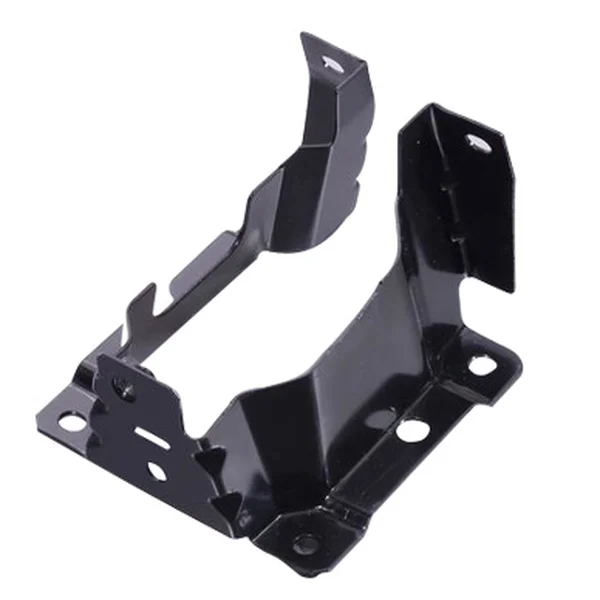
A 2.0 mm multi-bend bracket is a tolerance stack before it is a part
The engineering problem with a custom bent sheet metal stamping bracket is rarely the bends themselves. A press brake can hold an angle to half a degree all afternoon on a 2.0 mm cold-rolled bracket with two or three simple bends. What decides whether the part fits is everything that moves when the metal is formed: the neutral axis shortens, the flange grows longer than the flat pattern predicts, the hole near a bend line drifts with the bend allowance, and the last bend re-maps every hole that came before it. Put those effects in series and a bracket that is dimensionally perfect on the print can arrive at assembly 1.5 mm out of position, and the error will not look like a bend problem. It will look like a hole pattern problem.
We stamp and form these in 2.0 mm cold-rolled steel, holding bend-to-hole at +/-0.10 mm and bend angle at +/-0.5 degrees, with every critical dimension gauged and reported. This page is for the engineer who decides how the bracket is dimensioned, because on a multi-bend part the drawing is the tolerance scheme.
Bend allowance is a formula with a variable nobody measures
Every flat pattern is built from three terms: the outside flange dimension, the bend deduction, and the bend allowance. The bend allowance is set by the K-factor, and the K-factor is not a physical constant of the material – it is the ratio of neutral axis offset to thickness that the process happens to produce for that radius, that material, that tooling and that operator. A K-factor of 0.33 is common for cold-rolled steel at a moderate radius. Published tables run from 0.30 to 0.44 for the same material, because shops measure it differently and few shops measure it at all.
The consequence is concrete. If you release a pattern at K=0.33 and we form at an effective K=0.40, every 90-degree bend is longer than your pattern by roughly 0.07 x thickness x bend count. At 2.0 mm with four bends that is about 0.56 mm of extra flange length across the part. That does not show up as an error on any single flange, because each flange is still within its own tolerance. It shows up as the overall distance from the first hole to the last hole being half a millimetre long.
So the flat pattern should not be a fixed number if the part has four or more bends. State the developed length with the tolerance that absorbs K-factor variation – typically an additional +/-0.3 to +/-0.5 mm per bend pair – or ask the fabricator to develop the pattern from the model with their own verified K-factor and confirm the developed length as a single closed dimension. A bracket whose overall length is dimensioned “critical, +/-0.15” with a K-factor written beside it will arrive. A bracket with four separately toleranced flanges and no overall control will not.
Order of bends decides whether the part is even possible
Multi-bend brackets fail in planning far more often than in the press. The rule is absolute: bend from the fewest degrees and smallest radii to the most extreme, and leave the hardest bend until last, so the tooling holding final geometry is doing the hardest work. On a bracket with a 90-degree flange, a 45-degree gusset and a 90-degree return, the gusset is the difficult one – tighter effective radius, longer outside setback, and the bend most likely to be obstructed by an adjacent flange. Bend it first and the tool reaches into an awkward pocket on every part. Bend it last and it reaches a flat blank with nothing in the way.
The drawing should carry the bend order – not as a note, but as a numbered sequence with the angle and radius for each bend. A fabricator not told the sequence will assume the order the features appear on the print, which is usually the order a person drew them, which is usually the wrong order. Where a part cannot be formed in any sequence without interference, the honest answer is a relief notch, a tab, or a split bracket. Finding that at quotation costs nothing. Finding it after the die is cut costs the tool.
Second bends inherit the condition the first one left behind
That is easy for one bend and difficult for two on the same flange, which is why the angle tolerance here is +/-0.5 degrees rather than tighter. The second bend must overbend by an amount that accounts for the sheet now being partly work-hardened from the first, and work-hardened springback is higher than virgin springback. Apply the same rule to both and the flange lands out by roughly half a degree.
Where the bracket is stamped rather than entirely brake-formed the situation changes character. A forming die holds the angle by geometry and pressure distribution along the bend length, not by an operator’s judgement. That is more repeatable, and it is why a multi-bend bracket that must hold +/-0.5 degrees across a batch is usually better as a stamped-and-formed part in a dedicated die than as a pure brake part measured by protractor. It is also why the die is a separate cost line: it is a dedicated tool that has to be made, and it is what makes the angle repeatable.
Bend line versus hole position, and why the print has to forbid the overlap
The most common cause of scrap on a bent bracket is a hole too close to a bend line. The reason is geometric: when the sheet bends, material at the bend line is compressed inside and stretched outside, and a hole whose edge falls in that zone gets distorted. A 4.2 mm hole at 1.5 mm from the bend line in 2.0 mm steel comes out slightly oval and, more importantly, displaced toward the bend by an amount nobody dimensioned.
Set the minimum separation as a rule rather than leaving it to judgement. For 2.0 mm cold-rolled steel, keep hole edges at least 3 mm from the bend tangent line, and at least 1.5 x hole diameter from that tangent where the hole is a critical locating feature. If the design needs closer than that, the options are to move the bend, move the hole, or accept an elongated hole – legitimate for a fastener on a clearance hole, bad for a dowel or a locating pin.
The print should also treat hole position tolerance relative to the bend as different from the ordinary pattern tolerance. A pattern tolerance of +/-0.10 mm from the part datum is only achievable if the datum is stable and unbent. If the datum is a bent flange, that tolerance is measuring two effects at once and the drawing is ambiguous about which is failing. Pick datums on flat, unbent surfaces; a flat face in the middle of the blank is the most stable thing on the part.
What actually drives the cost of a multi-bend bracket
Three parts, behaving differently. Material is blank area times thickness times alloy price, and it is a small fraction of the total on any bracket with substantial forming. Tooling is the die, a fixed cost amortised over quantity. Per-part conversion is press time, deburring, and inspection.
The line that surprises people is tooling, because a four-bend stamped bracket is not a simple 90-degree punch. It needs a forming die with four distinct bend edges, cam or slide actuation if the bends are on different planes, spring or pressure pad support so the sheet does not lift, and sensors so the bend completes. If the part carries a formed flange and pierced holes in the same operation, the die also needs a stripper with proper heel pressure, and the piercing has to be sequenced so the stripper has somewhere to land. This is a real tool with real hours in it, and it should be quoted as a separate, refundable line with ownership stated.
The engineering question that actually changes the price is the bend tolerance, not the hole tolerance. Holding angle to +/-0.5 degrees across a batch requires in-die sensing or defined spring compensation in the tool; holding it to +/-2 degrees does not. A bracket whose only tight requirement is one locating hole and everything else is fastener clearance should not be paying for angle control across all four bends, and saying which features are critical lets the tool be simpler. Conversely, if the bracket interfaces with a mating assembly at two points, both points should be called out critical, because that is what justifies the sensing.
Sample approval is where the money is saved. A first article measured against a signed drawing, with every critical dimension reported, catches a wrong K-factor, a reversed bend order, and a hole that drifted – all three corrected at sample stage, before production starts on your written sign-off. The alternative, discovering the pattern error at 500 pieces, is not a correction, it is a re-run.
Questions that decide whether this bracket is buildable
When a multi-bent bracket comes back for drawing review, these are the questions that change the part rather than confirm it, and they are worth asking in writing before the die is cut.
- Is the flat pattern a controlled dimension with a stated K-factor, or an unchecked calculation?
- Is the bend order stated, and does the physical tool have clearance for every intermediate state?
- Does any hole edge sit closer than 3 mm to a bend tangent line, and is that hole a clearance hole or a locating feature?
- Are the datums on flat, unbent surfaces, or do they depend on a bent flange?
- Which angles are genuinely critical to +/-0.5 degrees, and which can open to +/-2 degrees so the tool is simpler?
- Are there minimum bend radius violations – any internal radius below 0.8 x thickness on 2.0 mm steel?
- Are corner reliefs present at every flange intersection, and large enough to clear the punch?
- Is there a masking list for any hole or face that carries a fit?
- Do the two mating interfaces that matter most both carry the tight tolerance, or only one?
- Has the sample been measured against the released drawing with a report, and is the signed sample the gauge reference for later batches?
None of these is a request for information for its own sake. Each corresponds to a failure that is expensive to find late and cheap to design out, and that is the substance of quoting a custom bent bracket: the part is easy to form and hard to keep consistent, and the drawing is where consistency is either secured or quietly lost.
This part belongs to our Custom Metal Stamping Parts range. The custom metal stamping parts pages collect the process notes, common materials and inspection points behind every product in the family.
Specifications
| Item | Custom Bent Sheet Metal Stamping Bracket |
|---|---|
| Brand | AUNOV |
| Designing | Made to your 2D/3D drawings (PDF, DWG, STEP, IGS) – DFM notes come back with the quotation, and the approved print governs every later batch. |
| Tooling | Progressive and single-stage dies are designed and built in house, so the die charge is a separate, refundable quotation line, with ownership confirmed on the quotation. |
| Samples | Samples are issued for approval before the run, and any deviation is corrected at sample stage, Production starts only after your written sign-off. |
| Materials | cold-rolled steel, 2.0 mm; mill certificate and heat-number traceability supplied with the first article. |
| Surface finish | black powder coat; alternatives quoted against the drawing. |
| Processing | press brake + stamp – a multi-bend stamped bracket profiled. |
| Equipment | Press park 5-500 T (mechanical 5-250 T, hydraulic 250-500 T) with in-die sensing, press brake cells and an on-site toolroom. |
| Tolerance | ±0.10 mm bend-to-hole; ±0.5° bend angle; critical dimensions 100% gauged. |
| Delivery terms | Freight, Incoterm and payment term are confirmed on the order: FOB, CIF or DDP, T/T or L/C. |
Related Products
Request a Quote for This Part
Send a drawing or sketch — get material advice, tooling cost and a per-piece price within 24 hours (working days).