
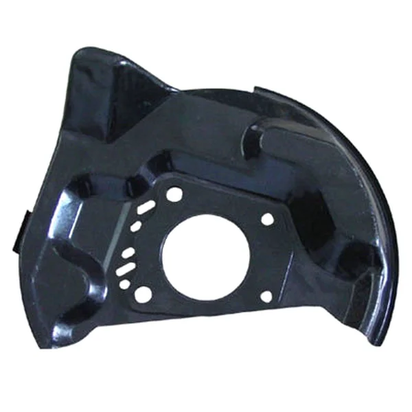
A large bore is a different tool problem from a small hole
At first glance a large bore should be the easy feature on this bracket. It is not, and the reason is a trade most people do not expect: as hole diameter grows relative to material thickness, the piercing force per unit of cut length rises sharply, because the punch has to act over a much larger circumference while remaining unsupported across that span. A 6 mm hole in 2.5 mm HSLA is a comfortably rigid punch.
The stiffness scales with the cube of thickness relative to span, which is why thickness matters so much here. Going from 2.0 to 2.5 mm on the same bore diameter raises punch stiffness by roughly 95 %, and that is the difference between a bore that holds ±0.08 mm and one that wanders into ±0.20 mm across a production run.
- Support behind the bore — a bolster or a wear plate directly behind the bore line removes most of the deflection term for very little cost, and it is the first thing to add when a large bore is out of tolerance.
- Punch geometry — a stepped punch with a thicker cutting section and a relieved body deflects less than a straight-walled punch of the same diameter.
- Cutting sequence — piercing the bore as a single shot in the flat blank is far better than forming it or piercing it after the slot array has already relaxed the material around it.
- Burr orientation — on a large bore the burr is proportionally more visible and more likely to interfere with whatever the bore locates. Plan which face it lands on.
Bore ovality is a punch deflection problem wearing a tolerance
Ovality — the bore measuring slightly longer in one direction than another — is almost always punch and die deflection rather than a material or machine problem. The bore is cut as a circle; by the time the shear has completed, the punch has flexed under the peak load, and the hole it produced is very slightly non-circular.
Three things drive it, and they are worth separating because they have different fixes. First, punch deflection at peak load, which is a stiffness problem. Second, die deflection, which on a large bore is a support problem — the die block under a big cut ring carries a large reaction and needs to be stiff over the whole area, not just at the edge.
The practical sequence for correcting an out-of-tolerance bore is to add support first, because it is cheap and reversible; then increase punch section stiffness; only then look at the press. Going straight to a bigger press is the most common mistake, and it is usually wasted money, because a 30 % tonnage increase on this operation may buy nothing if the die block is the flexible element.
There is also a measurement point worth raising. A CMM reports the bore as a fitted circle or as a set of points, and the two give different ovality numbers on the same part.
A slot array next to a large bore accumulates error differently
This bracket carries both a large bore and a slot array, called to ±0.10 mm, and the two features fail in different ways. The bore is a single feature whose error is dominated by tool deflection during its own cut.
The consequence is that on this part the bore can be in tolerance while the far end of the array has drifted, or the reverse. Any inspection plan that checks one hole and one slot has not necessarily checked the pattern. The array needs a span callout — the position of the last slot relative to the first, or relative to the bore — because that is the dimension that actually goes out.
- Pitch error accumulation — with index pitch variation around ±0.02–0.03 mm, an array spanning six stations inherits up to roughly 0.15 mm of accumulated pitch error before any process variation. That alone consumes the whole ±0.10 mm band.
- Thermal growth — a continuous die running warm on a 300 mm line can add 20 µm of growth. On a bracket with a dense array this is a first-order effect, and it is why the first article and the four-hundredth article differ.
- Slot-to-bore reference — dimensioning the array from the bore rather than from the array’s own first slot ties the two features together and prevents them drifting apart independently.
- Springback from the formed flange — any flange formed after the pierce moves the pierced features relative to the formed ones. Ordering the bore and the array late in the sequence costs stations but buys accuracy.
Where the design allows a choice, the strongest move is to make the bore and the first array slot share a single pierce station relationship, so that at least one dimension in the pattern is guaranteed by the die rather than by the accumulated pitch. Everything else in the array is then referenced to that pair.
Why we sometimes machine the bore instead of stamping it
There is a point at which piercing a bore to ±0.08 mm stops being the right answer, and it is worth being explicit about where it is so nobody wastes an argument. Pierced bores hold ±0.08 mm repeatably when the punch is stiff, the die is supported and the material is thick enough relative to the span.
The cost comparison is not simply per-part price. A machined bore adds a secondary operation, a fixture, an extra datum and a handling step. What it buys is an accuracy that is essentially independent of the stamping process, which has a particular value when the bore is the part’s primary locating feature.
The middle route is also common: pierce the bore to a generous tolerance and use a reamer or a short-cycle die in the same station sequence to bring it into tolerance. That keeps the part in the press cell and avoids a second handling, at the cost of a slower station and a tool that needs more frequent replacement.
- Pierce then finish in-die — keeps the datum chain intact and the part in one operation; needs a good bushing and a reaming allowance around 0.1 mm on diameter.
- Pierce then machine — strongest accuracy, adds an operation and a second datum; worth it when the bore is the primary locating feature.
- Pierce and accept — correct when the bore locates nothing and the tolerance is genuinely loose relative to the assembly. Cheapest, and the option most often left unexplored because nobody asks what the bore is for.
The question that settles it is simple: what does this bore locate, and what tolerance does that consumer actually need? Send us the mating part or the assembly drawing and we will tell you which of the three routes we would quote, including the case where the answer is the cheapest one.
HSLA at 2.5 mm sets a piercing clearance window that is genuinely narrow
Side clearance between punch and die on this material runs around 5–8 % of thickness, which for 2.5 mm is 0.13–0.20 mm per side. Narrow, but not unreasonably so. The reason the window is narrow is that HSLA work-hardens faster than mild steel during the shearing cycle, and a material that is work-hardening at the cut face will tear rather than shear if the clearance is too small.
At the other end of the window, excessive clearance produces a rollover on the entry side and a tapered hole wall. On a bore that locates something, the taper matters because the hole is no longer a cylinder and the fit becomes direction-dependent.
- Burr height — on 2.5 mm HSLA typically 0.06–0.12 mm. Where the bore takes a fastener or a press-fit, plan the piercing direction so the burr is not on the bearing surface.
- Punch edge condition — burr height grows measurably once the punch breaks. On a high-volume bracket the regrind interval is a planned maintenance item with a number attached, not a judgement call on the shop floor.
- Break edge — 0.3–0.5 mm on the punch shoulder controls entry rollover and costs almost nothing.
- Lubrication at the pierce — HSLA galling against a tool steel die is real, and galling on the die button shows up as both a burr problem and a wear problem within a fraction of the expected tool life.
The wear consequence on the bore specifically is worth noting. A large bore wears at its edge, and edge wear on a large diameter produces a slowly growing taper rather than a sudden failure. Taper does not trip a go/no-go gauge set at nominal size until it has already consumed most of the tolerance band.
Two failure modes that show up in service rather than on the CMM
On this bracket, the dimensional requirements and the failure modes do not line up neatly, which is worth walking through explicitly at the design review.
The first failure is fretting at the bore. A bore at ±0.08 mm on position but carrying a loose fit will fret under vehicle vibration, and the fretting debris then works into the fit and makes it looser. This is a clearance problem that presents as a durability problem, and the fix is a clearance change rather than a tolerance change — tightening the position tolerance would not have prevented it.
The second is slot-to-bore fretting. The array at ±0.10 mm locates relative to the bore, but if the array is only loosely located in its mating feature, relative motion under vibration produces fretting at the slot roots, where stress concentrates. Slot roots on a pierced slot are already a stress raiser because the material there is work-hardened and slightly torn from the shearing.
- Work-hardened slot roots — a torn shear edge has lower ductility than the parent material. If a slot carries a bending load, specify a generous root radius and consider a coined or rolled edge.
- Bore surface finish — a punched bore carries the rolled layer from the shearing cycle. Where it locates a bearing or a seal, that layer is sometimes unacceptable and a light finishing pass is needed.
- Coating on a pierced bore — plating a bore reduces its diameter by the coating thickness on each wall and can bridge a small bore. Masking the bore, or plating before piercing in a two-operation route, avoids the problem.
- Handling of a large unsupported bore — a large bore weakens the surrounding section, and a bracket with a big bore can be damaged in handling while remaining dimensionally perfect. This is a packaging and fixturing question, not a drawing question.
None of these are visible on a CMM report. They are the reasons a bracket can be dimensionally correct for its entire life and still generate a warranty claim, and they are the reason the drawing review should ask what the bore and the slots do rather than only how big they are.
Tooling, samples and the cost of holding ±0.08 mm at volume
Holding a bore to ±0.08 mm and an array to ±0.10 mm on 2.5 mm HSLA is achievable, and the cost drivers are knowable in advance rather than discovered later.
- Die construction — the bore station needs more support mass than a typical piercing station, and the array needs tighter feed accuracy. Both are toolroom decisions that show up in the die quotation.
- Punch material — a carbide or coated punch on the bore station costs more up front and buys life. On a large bore where edge wear produces taper rather than sudden failure, tool life translates directly into how often the tolerance band is at risk.
- Feed and indexing — where the array pitch is the limiting factor, the feed system is a legitimate target for spend. A better feed costs less over a programme than the scrap from a drifting array.
- Sample discipline — first articles ship with a dimensional report and a material certificate, and later batches are gauged back to the signed sample. That reference only works if the signed sample is a production-intent part.
On the commercial side, the die charge here stays in our own toolroom with ownership confirmed on the quotation, which keeps it transparent and lets a die be re-cut from the original design data if the bracket is ever revised.
The honest summary is that ±0.08 mm on the bore is comfortably inside what this material and thickness can do in a well-supported die, and the risk is not capability but drift — wear, thermal growth and pitch accumulation, all of which are managed rather than eliminated.
This part belongs to our Custom Metal Stamping Parts range. The custom metal stamping parts pages collect the process notes, common materials and inspection points behind every product in the family.
Specifications
| Item | Stamped Automotive Seat Side Bracket with Large Bore |
|---|---|
| Brand | AUNOV |
| Designing | Built to the drawing you supply – unusual walls, piercings or tolerances are feasibility-checked first, and the approved print governs every later batch. |
| Tooling | Die, fixture and gauge work stays in our own toolroom, which keeps tooling cost transparent, with ownership confirmed on the quotation. |
| Samples | First-article samples ship with a dimensional report and material certificate, and any deviation is corrected at sample stage, Later batches are gauged back to the signed sample. |
| Materials | HSLA steel, 2.5 mm; mill certificate and heat-number traceability supplied with the first article. |
| Surface finish | The drawing selects the finish: plating, coating, anodising or passivation, with masking and laser marking available where needed. |
| Processing | progressive stamp – a seat side bracket combining a large bore. |
| Equipment | 5-250 T presses running progressive and compound dies; first articles and batch samples are checked on the CMM. |
| Tolerance | ±0.08 mm bore; ±0.10 mm slot array; critical dimensions 100% gauged. |
| Delivery terms | Delivery quoted per Incoterms 2020 – FOB, CIF or DDP – by sea or air, to your address. |
Related Products
Request a Quote for This Part
Send a drawing or sketch — get material advice, tooling cost and a per-piece price within 24 hours (working days).