
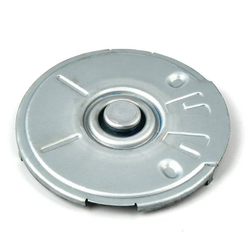
Shallow draw, then trim: the hole pattern changes at the trim
This cover is made in two distinct operations and the tolerance scheme has to survive both. The blank is shallow drawn into a domed shell with a return flange; the shell is then trimmed to the finished outline and pierced. On paper the drawing shows a domed centre, a flange and a hole pattern, and the hole pattern looks like a set of holes. In the process, those holes are cut in the second operation, at a point where the part has already been formed, is springy, is not yet fixtured, and has a wall thickness that varies around the dome.
Each of those four facts moves the holes. The domed geometry means a pierce made from above is not perpendicular to the local surface. The springiness means the part moves under the punch force. The varying wall means the pierce shears a section whose thickness changes across the dome. And the trim that defines the outline happens in the same handling, so whatever distortion the trim introduces is present when the holes are made. A hole pattern toleranced at +/-0.10 mm on a 1.2 mm SPCC cover is achievable, but only if the trim is complete before the pierce and the pierce happens in a fixture that locates on the finished geometry.
We draw these in 1.2 mm SPCC cold-rolled, trim and pierce them, hold dome height to +/-0.08 mm and the hole pattern to +/-0.10 mm with critical dimensions 100% gauged, and finish in clear zinc or natural. This page is about the process window at 1.2 mm and about the order of operations the hole pattern actually depends on.
1.2 mm is thin enough that the process window is genuinely narrow
- Wrinkling happens when the flange is not held firmly enough, so draw-in material has nowhere to go and buckles. On a shallow draw it appears as a concentric fold a few millimetres inside the flange edge, and on a cosmetic cover it is an automatic reject because it shows in reflection under the lighting the customer uses.
- Tearing happens when the blankholder holds too firmly, so material cannot feed and strain concentrates – typically at the corner radius where the dome meets the flange, or at the blank edge itself. On 1.2 mm it shows as a split running circumferentially from the blank edge, or a crack at the dome root.
- Between them is a window that on 1.2 mm low-carbon steel spans a few hundred kN on a 100-tonne-class draw, which sounds wide until you remember it narrows as the dome gets deeper, as the flange gets narrower, and as the material gets harder.
- Specify the temper. SPCC annealed or quarter-hard has a wide window; half-hard or full-hard has a much narrower one, and on 1.2 mm the difference between quarter-hard and half-hard is the difference between a robust process and a marginal one. If the design needs the springiness of a harder temper, that has to be stated – otherwise the shop buys whatever is on the shelf.
- State the thickness band. 1.2 mm SPCC ordered to a general tolerance is a wide band, and the draw is set up for the middle of it. The thickest material in the band wrinkles at a force set for the average; the thinnest tears. That is arithmetic, not a defect, and it is why the band is a drawing requirement rather than a purchasing detail.
Dome height at +/-0.08 mm is set by blankholder stroke, not die geometry
The dome height tolerance is unusually tight for a drawn shell, and understanding why explains what has to be controlled.
On a shallow draw the part is not held to its height by the die – the die is bottomed. It is held by the blankholder. The blankholder pushes down, metal between the draw rings stretches, the dome forms, and the final height is where material equilibrium lands once the blankholder stops. The relevant number is blankholder stroke, and the die does not set it.
The controls that matter, in order of importance:
- Blankholder stroke position. The direct control, repeatable to well under 0.1 mm on a press with a defined stop – provided the stop is not being used to absorb material variation, which it will be if the thickness band is wide.
- Incoming thickness. A thicker blank stretches less for the same geometry, so the dome stands slightly higher. Across a thickness band this is a real, repeatable contributor.
- The gap between blankholder and die in the draw rings. Too tight and the material is pinched and stretched harder than intended; too loose and the flange wrinkles. A gap tight at one station and loose at another produces a dome that is not symmetric about the axis.
- Lubrication and blankholder friction. Higher friction means more stretching and less draw-in, so the dome ends higher. Lubricant variation is a real and underappreciated contributor to a dimension nobody thinks is friction-dependent.
To hold +/-0.08 mm the practical requirements are a press reporting blankholder position or tonnage against a defined window, a stated thickness band, a defined lubrication specification, and an inspection method that does not itself add variation. That last one matters more than expected: dome height measured with a depth mic on a part not resting on a known flat will vary by the deflection of the part under the mic’s foot, which on a 1.2 mm shell is easily a tenth of a millimetre. The print should state the support method and the gauge force.
Locating bosses are the hard part of the draw
Bosses are what a downstream assembly registers against, and they are the least forgiving feature on the drawing for three reasons that compound.
- A boss is a local draw, not a global one. Every millimetre of boss height is extra draw depth in that local area while the surrounding dome stays put. The boss sidewall is pulled at a different rate from the adjacent panel, and the boss root is a stress concentration exactly like a dome root. On 1.2 mm the boss root radius needs to be generous for the same reason the dome root does.
- Boss height varies more than dome height. A boss forms over a small area, so its material comes from a narrow annulus around it, and any variation in local draw-in shows directly as a height change. A boss toleranced at the same band as the dome will be harder to hold and should not be.
- A boss is a datum, and a forming tolerance is a poor datum tolerance. If anything locates against the boss face, the boss height becomes a functional dimension with an accumulated chain of dome height, boss height and their relative position. If the total exceeds what the assembly accepts, the fix is a machined or formed-flat pad, not a tighter draw.
Trim before pierce, and the hole pattern that depends on it
- Normal-angle error. A pierce made from above at the crown of a domed panel meets the local surface at an angle rather than square. The hole axis follows the punch, so the hole is cylindrical but its position in the panel is offset from the punch axis by the dome slope over the local dome height. On a dome rising 8 mm over a 40 mm radius the slope is about 11 degrees, and a punch axis tilted 11 degrees off panel normal shifts the hole by the dome height times the tangent – of the order of 0.8 mm for a 20 mm tall dome. The hole is in the wrong place by that much unless the fixture presents the punch normal to the local surface.
- Spring-back of the pierced panel. A panel with a pattern of holes has less stiffness between them, and a shallow dome with holes relaxes slightly when released from the draw. If holes are pierced while the panel is constrained in a die, the panel relaxes afterwards and the hole spacing changes. That is why pattern on a formed panel should be inspected on a relaxed part, and why a pattern measured in the die is not the finished condition.
- Trim-induced distortion. Trimming releases the constraint of surrounding material, and a panel moves. The pattern has to be toleranced on the trimmed part, because that is the part that gets assembled; a pattern dimensioned on the pre-trim condition is not verifiable on the delivered part.
Burr direction is a drawing decision, not a shop detail
Clear zinc on 1.2 mm, and where the film thickness shows up
- Vent openings. A plating film plus passivate reduces open area slightly and, on small slots, measurably. If an open area figure is functional, it should be the post-finish figure.
- Sealing face. The flange face that seals against the frame needs continuous coverage; a masked face here is a leak path.
- Tapped holes. On 1.2 mm the thread engagement is short, and plating materially reduces it. A tapped hole on this thickness should either be masked or specified as plated, with the thread class stated.
Where this drawing usually stops short of the real question
These are the points where the drawing is likely to be silent and where the silence creates a decision made by default on the shop floor.
- Is the pierce specified as coming after the trim, and is the fixture shown to present the punch normal to the local dome surface at each hole?
- Is the hole pattern toleranced on the trimmed, relaxed part rather than in the die?
- Is burr direction stated, and is blank orientation fixed so it does not alternate?
- Is the dome root radius at least 3 mm on 1.2 mm material, and is the boss root radius comparable?
- Is the thickness band stated, and is the temper stated? Without both, the draw window is a guess.
- Is dome height measured on a defined support with a defined gauge force, and is flange flatness measured on the assembly plane?
- Are boss heights toleranced separately from dome height, and does the assembly’s acceptable stand-off range actually hold when those tolerances accumulate?
- Are the sealing face, locating pads and any tapped hole correctly assigned in the masking list?
- Is open area given as a post-finish value, with the deburring method specified so tumbling cannot close it?
- Is the first article sectioned to show wall thickness at the dome root and boss roots, with a minimum stated?
The first question changes the part. Trim-then-pierce with a fixture that matches the dome is the difference between a hole pattern that is a stamping dimension and one that is an accumulation of forming and trimming tolerances – and it is decided by a single line in the process plan that nobody writes unless somebody asks.
Sizing the draw for a part like this — reduction per station, ironing allowance, flange width — is covered step by step in our deep drawn covers guide.
Specifications
| Item | Stamped Steel Shallow Drawn Motor Cover |
|---|---|
| Brand | AUNOV |
| Designing | Quoted from your print, not a catalogue – DFM notes come back with the quotation, so changes are priced before tooling is cut. |
| Tooling | Die, fixture and gauge work stays in our own toolroom, so the die charge is a separate, refundable quotation line, and lead time is measured from tooling start. |
| Samples | Pre-production samples come with a full inspection report, so the shallow drawn motor cover is proven before volume production, Later batches are gauged back to the signed sample. |
| Materials | SPCC cold-rolled steel, 1.2 mm; mill certificate and heat-number traceability supplied with the first article. |
| Surface finish | clear zinc or natural; alternatives quoted against the drawing. |
| Processing | shallow draw + trim – a shallow-drawn steel cover with a domed centre and locating bosses. |
| Equipment | Press shop with 5-250 T mechanical presses and dedicated dies, backed by CNC turning centres and a climate-controlled inspection room. |
| Tolerance | ±0.08 mm dome height; ±0.10 mm hole pattern; critical dimensions 100% gauged. |
| Delivery terms | FOB Ningbo or Shanghai; T/T, L/C at sight or D/P; repeat orders reuse the approved first article. |
Related Products
Request a Quote for This Part
Send a drawing or sketch — get material advice, tooling cost and a per-piece price within 24 hours (working days).