
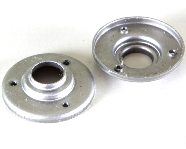
A spun bearing seat is a part where two datums compete
The bearing seat is machined after spinning, because spinning cannot hold a bore to a fit tolerance and cannot produce a running surface finish. And the moment a machined bore and a spun rim must be related to each other, the datum question is forced. Is the bore machined in the same setup as the diameter that locates it, or relative to the rim spinning already made? These are different tolerances, different costs and different risks, and which one you get depends on how the process route was decided, not on how the drawing was drawn.
We spin these in 2.0 mm steel or aluminium, holding rim runout to +/-0.08 mm with concentricity held by the mandrel, critical dimensions 100% gauged. This page is about the datum chain on a spun ring – where it starts, what it inherits, and which of the two places to put the machining that most often gets put in the wrong place.
What spinning gives you and what it cannot
The properties of a spun surface follow from the fact that material is formed over a rotating mandrel by a tool, in continuous rotational contact rather than in a discrete punch stroke. Which properties come from that is worth being specific about.
- Roundness is excellent and comes from the mandrel. No punch strikes the material at a discrete location, so there is no local indentation and no die-closing mark. Runout is limited by the mandrel’s runout and by how concentrically the tool tracks it, not by the forming operation.
- Work hardening is severe and one-sided. The tool contact face hardens far more than the mandrel face. On a ring that will be machined, the hardened layer on the face being cut changes tool wear significantly and is why a spun face is not efficient machining stock.
- Wall thickness only ever decreases. No operation in spinning thickens a section. Whatever thickness the blank had, the wall is thinner and the flange retains closer to blank thickness.
Those five points determine the process route for a bearing seat ring before anyone draws anything. The body of revolution is spun; the features that break symmetry are machined or stamped; the surfaces carrying a fit are machined; and the machining must be designed around the fact that the stock it is cutting is work-hardened on one side and not the other.
The datum chain, drawn out in full
- Mandrel axis. The part is formed on this, and every roundness and concentricity figure on the as-spun part derives from it. This is the best datum in the whole process and it disappears once the part is off the machine.
- As-spun outside diameter. Round and coaxial to the mandrel. Usable as a locating feature, but a surface of revolution with a drawn grain and a lightly crowned profile, so a chuck gripping on it grips on a variable diameter.
- As-spun rim face. Square to the axis to within the spinning’s capability – this is where the +/-0.08 mm runout figure comes from. An excellent seating reference, but not a precision locating face and it cannot be used as one.
- Machined locating step or register. Created specifically so the finished features have a repeatable reference. This is where the datum should be changed over.
- Machined bore and rim face. The functional features, cut in one setup from the register, so their relationship is held directly.
The error that costs money is putting link 2 or link 3 in the middle of the chain instead of link 4. A bore machined from the as-spun outside diameter must hold position relative to a surface whose diameter varies along its length by the draw-in variation of the spinning, and any variation there becomes bore position variation. At +/-0.08 mm on rim runout that is not a subtle effect.
The other error is not changing the datum at all – machining the bore first, then turning the rim face in a second setup because the part is easier to hold that way. Two setups means bore-to-face perpendicularity is now the sum of two fixture errors, and the register that would have made it a single-setup relationship no longer exists. This is the standard route by which a spun ring ends up with an apparently in-tolerance bore and an assembled runout that will not hold a shaft straight.
Rim runout is a definition problem before it is a manufacturing problem
The tolerance on this part is stated as rim runout, and the term needs pinning down, because two reasonable readings give two different engineering outcomes.
- Face runout at the rim – total indicator reading of the rim face as the part is rotated about its axis, referenced to the axis established by the fixture or by the bore. This is the reading that predicts whether the seated ring will wobble.
- Radial runout of the rim OD – variation in rim diameter as it is rotated. This predicts sealing and concentricity, not seating.
- Clamping force. A spun ring is thin at the rim by definition, because the wall is thinner than the flange and the rim is where material has been drawn out. Clamp it hard and it distorts, so the measured runout includes an induced term that is not the part’s fault and will not reproduce on the shop floor.
- Temperature. A thin ring is sensitive to a customer’s hand on it. Runout measured on a handled part is not runout.
- Where the indicator sits. On a crowned rim, runout at the OD edge and runout at mid-flange differ. The measurement location is part of the specification.
Specify it as: total indicator reading at a stated radius, referenced to the bore axis, part free of clamping, at a stated temperature. Without those clauses a report is evidence of nothing.
Aluminium and steel behave differently on the same drawing
This ring is quoted in either steel or aluminium, and the material choice changes more than the cost. Three differences affect design and process route.
- Formability. Aluminium spins easily in annealed or quarter-hard condition with a wide working window. Steel at the same 2.0 mm needs more passes and inter-pass annealing because it work-hardens faster and has a narrower window. A geometry comfortably spinnable in aluminium may need a preform pass in steel.
- Wall thickness distribution. Aluminium follows the tool more closely, so the wall is closer to tool geometry and more predictable. In steel more of the deformation goes into the material rather than into shape change, so the wall thins less predictably and the rim varies more.
- Machining after spinning is the largest practical difference. Aluminium machines fast and the work-hardened layer causes only modest tool wear. A spun 2.0 mm steel rim is a hard work-hardened surface over a soft substrate, which produces rapid flank wear and a tendency to leave a burr. If the rim face is to be machined concentric to a bore in steel, expect to specify a coated insert and a dedicated finishing pass, and expect that pass to determine whether the runout tolerance is comfortably held or marginally held.
Residual stress, and why the parts move after machining
Spinning leaves the part stressed. The face the tool touched is in compression, the mandrel face in tension, and the flange carries bending stresses from being pushed radially outward. The part looks finished and is not dimensionally settled.
- Stress-relief anneal after spinning, before any finish machining. On steel a defined operation at a temperature below the temper; on aluminium a stabilising bake. Needed for the same reason either way.
- Symmetric material removal where the design allows. A flange machined on one side only is always the unstable version.
- A defined settling period between finishing and final inspection for parts that arrive close to a size change, so the report reflects a settled part rather than a fresh one.
On a bearing seat ring this is not academic. The rim is clamped between the bearing and the housing, and a rim face that moves 0.05 mm after assembly has been inspected will change the clamping force on the bearing and eventually its preload. That is a service-life failure that started as a missing stress-relief operation.
Questions that decide the process route on this ring
These are the points where the drawing and the process plan have to agree, and where an unresolved answer becomes either a tolerance nobody can hold or a part heavier than it needs to be.
- Is the bearing bore machined from a machined register, or relative to the as-spun outside diameter?
- Is the rim runout figure a face runout or a radial runout, referenced to which axis, measured free or clamped, at what radius?
- Is there a stress-relief anneal between spinning and finish machining, and has the material been specified for it?
- For steel, how many spinning passes are planned and is inter-pass annealing in the route?
- Is the minimum wall stated at the rim, where material is thinnest, with its location identified?
- Are bolt holes or any feature breaking symmetry machined or stamped, and referenced to the same register as the bore?
- Is the rim face finish machined on both sides or one, and machined concentric to the bore in the same setup?
- Does the surface lay from spinning need addressing for coating, bonding or sealing?
- Is coating masked at the bore, register and rim face, with thickness stated as a range and a method?
- Is the settled condition – after stress relief, machining and any coating – defined for the final inspection?
The first two questions are where almost all the avoidable rework on this part comes from. The datum choice determines whether a single setup can hold the bore and the face together, and the runout definition determines whether the customer measures the number that was quoted.
Custom Metal Stamping Parts is the parent range for parts like this one; the overview page gathers the tooling logic, finishing options and tolerance notes that apply across the family.
Specifications
| Item | Custom Spun Metal Flanged Ring Bearing Seat |
|---|---|
| Brand | AUNOV |
| Designing | Quoted from your print, not a catalogue – the die is planned around your critical features, and the approved print governs every later batch. |
| Tooling | Progressive and single-stage dies are designed and built in house, so a die can be re-cut from the original design data, and lead time is measured from tooling start. |
| Samples | Pre-production samples come with a full inspection report, and the approved first article becomes the gauge reference, Production starts only after your written sign-off. |
| Materials | steel or aluminium, 2.0 mm; mill certificate and heat-number traceability supplied with the first article. |
| Surface finish | natural or clear zinc; alternatives quoted against the drawing. |
| Processing | metal spinning – a spun flanged ring rolled to a smooth concentric rim that seats a bearing or seal. |
| Equipment | Press park 5-500 T (mechanical 5-250 T, hydraulic 250-500 T) with in-die sensing, press brake cells and an on-site toolroom. |
| Tolerance | ±0.08 mm rim run-out; concentricity held by the mandrel; critical dimensions 100% gauged. |
| Delivery terms | FOB with DDP offered for EU and US addresses; payment T/T or L/C, freight quoted to destination. |
Related Products
Request a Quote for This Part
Send a drawing or sketch — get material advice, tooling cost and a per-piece price within 24 hours (working days).